
Novel mechanical arm joint

A technology of manipulators and joints, applied in the field of manipulators, can solve the problems of weak ability to change according to requirements, small driving torque, and influence of swing angle of manipulator joint shafts, etc., to achieve large output torque, ensure output torque, and guarantee The effect of swing angle

Pending Publication Date: 2018-10-16
WUHAN UNIV OF SCI & TECH
View PDF0 Cites 5 Cited by
  • Summary
  • Abstract
  • Description
  • Claims
  • Application Information

AI Technical Summary

Problems solved by technology

[0002] The robotic arm is currently the most widely used automated mechanical device in the field of robotics, while traditional robotic arms are designed based on specific tasks and cannot be changed and adjusted flexibly, and their ability to change according to requirements is weak
In the existing industrial robots, most of the multi-degree-of-freedom movements are driven by the servo motors of each joint, and the main problem in production is that the driving torque generated by the servo motors at each joint is small, but if the increase The output torque of the joint axis may affect the swing angle of the joint axis of the manipulator

Method used


Image

  • Novel mechanical arm joint
  • Novel mechanical arm joint
  • Novel mechanical arm joint

Examples


Embodiment Construction

[0023] Below in conjunction with accompanying drawing and specific embodiment, the present invention will be further described:

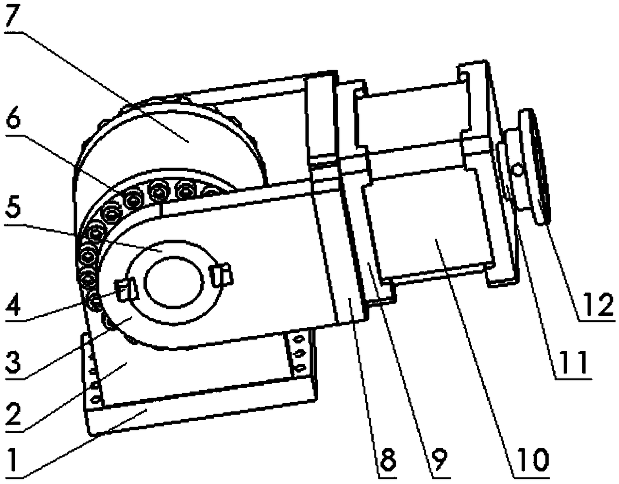
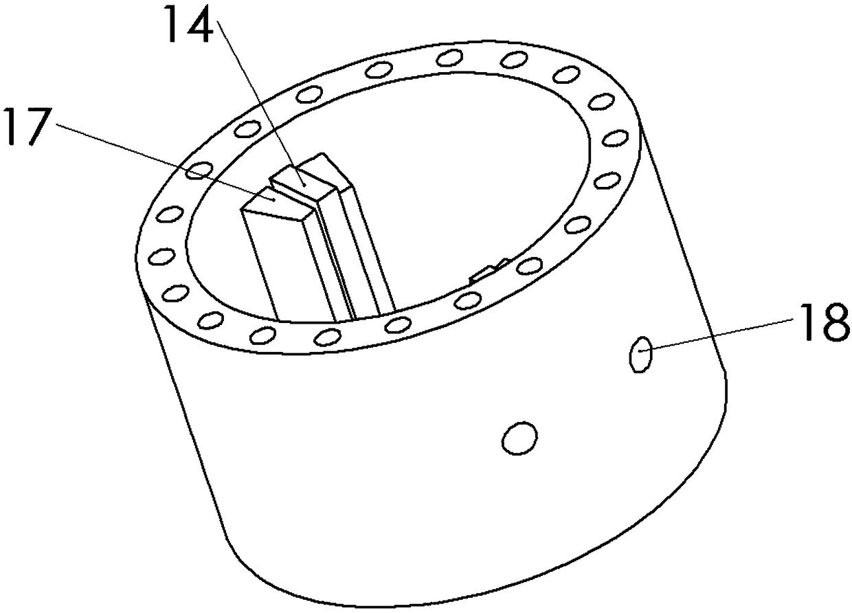
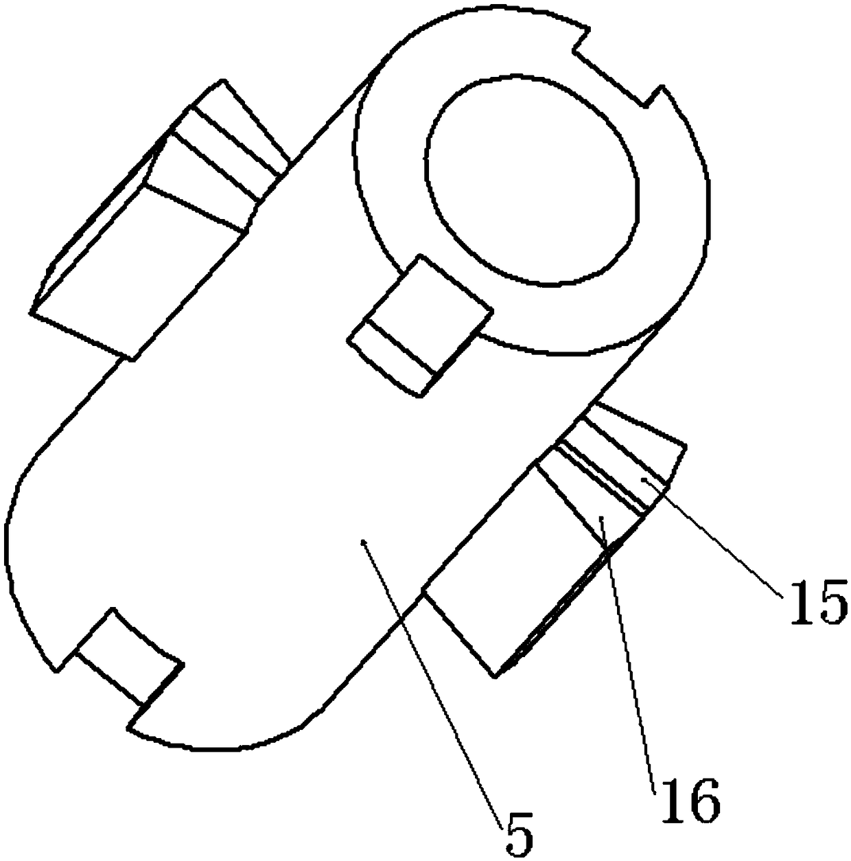
[0024] Such as figure 1 , 4 , 5, a new type of mechanical arm joints, including swing cylinder drive and servo motor drive.

[0025] The swing cylinder driving device includes a cylinder body 7 , a swing cylinder rotor 5 , a cover plate 2 , and a cover plate connecting plate 1 . Two of the cover plates 2 are respectively installed on both sides of the cylinder body 7 through several cover plate screws 6 to seal the inside of the cylinder body 7 . A through hole is opened on the cover plate 2, the swing cylinder rotor 5 is installed in the cylinder body 7, and both sides protrude from the through hole. The cylinder body 7 is mounted on the cover connecting plate 1 through two cover plates 2 .

[0026] The two sides of the swing cylinder rotor 5 are equipped with a force arm rod 3 , and the end of the force arm rod 3 away from the swing cylinder r...


PUM


Abstract

The invention discloses a novel mechanical arm joint. The novel mechanical arm joint comprises a swinging oil cylinder driving device and a servo motor driving device, wherein two cylinder body bladesupports which are symmetrically distributed are arranged on the inner wall of a cylinder body of the swing oil cylinder driving device, the cylinder body blade supports are used for installing cylinder body blades, two rotor blade supports which are symmetrically distributed are arranged on the side wall of a swing cylinder rotor, and the rotor blade supports are used for installing the swing cylinder rotor blades, the swing cylinder rotor is installed in the cylinder body, and the two cover plates which are packaged on the two sides of the cylinder body are fixedly supported, the cover plates on the two sides of the cylinder body are installed on a cover plate connecting plate; a servo motor driving device is provided with two motor end covers which are fixedly installed on the two sidesof a servo motor body correspondingly, the servo motor body is connected with a motor output shaft, and an output shaft end flange plate is installed at one end, far away from the servo motor body, of the motor output shaft; and one end, far away from the motor output shaft, of the servo motor driving device is installed at the two ends of the swing cylinder rotor through two force arm rods. According to the arm joint, large torque and large output torque can be borne, and meanwhile, a relatively good swinging angle can be achieved.

Description

technical field [0001] The invention relates to the technical field of mechanical arms, in particular to a novel mechanical arm joint based on the combination of swing cylinder drive and servo motor drive. Background technique [0002] The robotic arm is currently the most widely used automated mechanical device in the field of robotics. The traditional robotic arm is designed based on specific tasks and cannot be changed and adjusted flexibly. Its ability to change according to needs is weak. In the existing industrial robots, most of the multi-degree-of-freedom movements are driven by the servo motors of each joint, and the main problem in production is that the driving torque generated by the servo motors at each joint is small, but if the increase is fully considered The output torque of the joint axis may affect the swing angle of the joint axis of the manipulator. Contents of the invention [0003] The purpose of the present invention is to design a mechanical arm d...

Claims


Application Information

Patent Timeline
IPC IPC(8): B25J17/02
CPCB25J17/0283
Inventor 袁凯谢良喜罗刚
Owner WUHAN UNIV OF SCI & TECH
Learn More