
Power supply circuit used for M-BUS (Meter-Bus)

A technology of M-BUS and power supply circuit, applied in the field of micro-power isolated power supply, can solve the problem of large input current, and achieve the effects of simple design, reduced circuit power consumption, and low cost

Pending Publication Date: 2018-10-12
MORNSUN GUANGZHOU SCI & TECH
View PDF0 Cites 0 Cited by
  • Summary
  • Abstract
  • Description
  • Claims
  • Application Information

AI Technical Summary

Problems solved by technology

[0004] In view of this, the present invention proposes a power supply circuit for M-BUS, which can effectively solve the problem of large input current of the M-BUS power supply circuit and reduce power consumption of the circuit

Method used


Image

  • Power supply circuit used for M-BUS (Meter-Bus)
  • Power supply circuit used for M-BUS (Meter-Bus)
  • Power supply circuit used for M-BUS (Meter-Bus)

Examples


no. 1 example

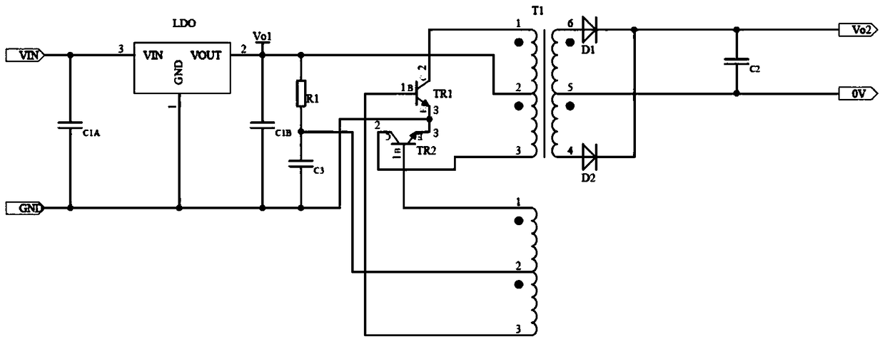
[0022] image 3 A schematic circuit diagram of the application of the present invention is shown.

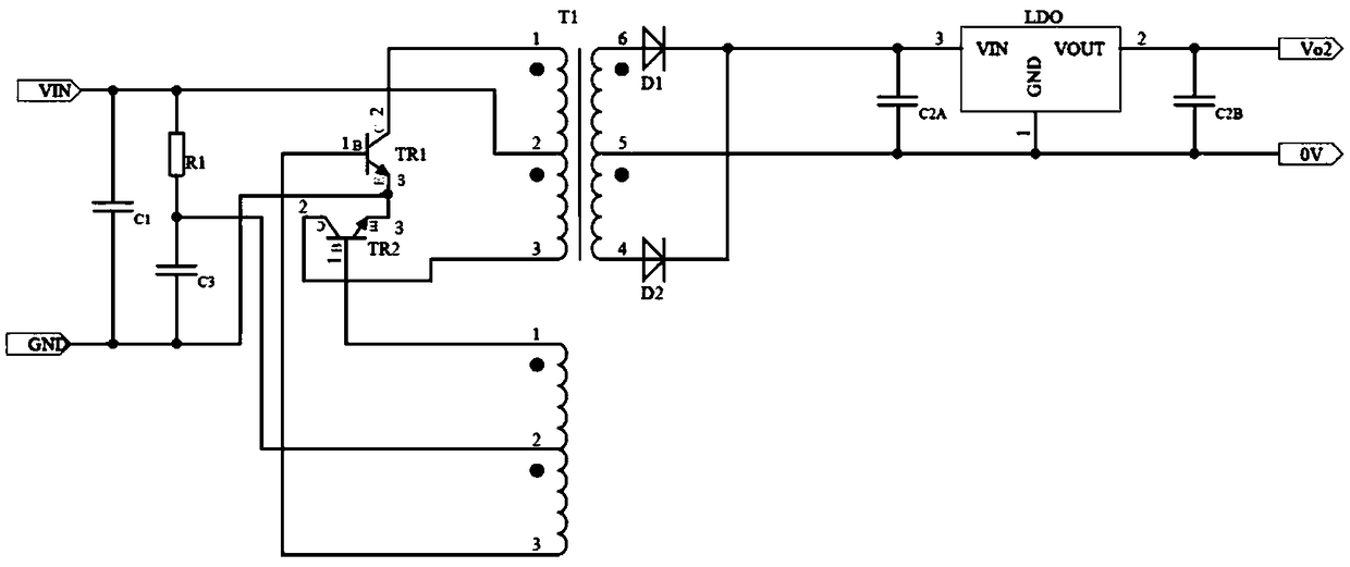
[0023] A power supply circuit for M-BUS, including a low-dropout linear regulator LDO, a Royer circuit, a filter capacitor C1A and a filter capacitor C1B; the input terminal of the low-dropout linear regulator LDO is connected to the input voltage, and the output terminal outputs a stable The voltage Vo1 is connected to the input terminal of the Royer circuit, and the ground terminal is connected to the input ground; the output voltage Vo2 of the output terminal of the Royer circuit supplies power for the M-BUS terminal, the filter capacitor C1A is connected between the input voltage and the input ground, and the filter capacitor C1B is connected to the LDO Between the output terminal and the input ground, C1A and C1B mainly play the role of filtering.

[0024] Described Royer circuit comprises triode tube TR1, TR2, transformer T1, diode D1, D2, electric capacity C2, C3 and res...


PUM


Abstract

The invention provides a power supply circuit used for M-BUS, wherein a low dropout regulator (LDO) is added at the front end of a Royer circuit, so as to separately output the external input voltagethrough the Royer circuit after the external input voltage is stabilized. The power supply circuit is simple and has low realizing cost; since the input voltage of the Royer circuit is stabilized on adefinite value by the front end LDO, the starting current of the Royer circuit is not affected by the external input voltage; the problem that the starting current is large when the high voltage is inputted in the prior power supply plan of connecting the LDO at the back end of the Royer circuit is effectively solved; thus, the input current is low and the output power is low; and the power supply circuit is very suitable to be used for the M-BUS that has micro power and needs the separated and regulated power supply.

Description

technical field [0001] The invention relates to an M-BUS power supply circuit, in particular to a simple, low-cost M-BUS micro-power isolated power supply. Background technique: [0002] M-BUS is a bus design specially used for utility meters. The M-BUS instrument bus can meet the special requirements of battery-powered or remote-powered metering instruments. When the measuring instrument receives the data transmission request, it will transmit the current measured data to the master station, and the master station will periodically read the data transmitted by these measuring instruments. Because the M-BUS works almost only when the terminal measuring instrument or counter sends data, and transmits the data to the general station, and in most cases the M-BUS is in the "standby" state, so it is used for the work of the power supply circuit of the M-BUS Most of the features are: 1. Low power consumption, generally at the milliwatt level; 2. The input current is small, and t...

Claims


Application Information

Patent Timeline
IPC IPC(8): H02M3/335
CPCH02M3/33569
Inventor 张彦斌冯刚尹向阳
Owner MORNSUN GUANGZHOU SCI & TECH
Learn More