Eureka AIR delivers breakthrough ideas for toughest innovation challenges, trusted by R&D personnel around the world.

Multi-battery switching method, power supply device, and electronic equipment

A power supply device and multi-battery technology, applied in battery circuit devices, arrangement of multiple synchronous batteries, circuit devices, etc., can solve problems such as differences in battery discharge characteristics, limited use scenarios, and impact on battery life and system performance, and achieve improvement Battery life and use time, the effect of increasing battery capacity

Active Publication Date: 2018-10-12
OPPO CHONGQING INTELLIGENT TECH CO LTD
View PDF2 Cites 10 Cited by
  • Summary
  • Abstract
  • Description
  • Claims
  • Application Information

AI Technical Summary

Problems solved by technology

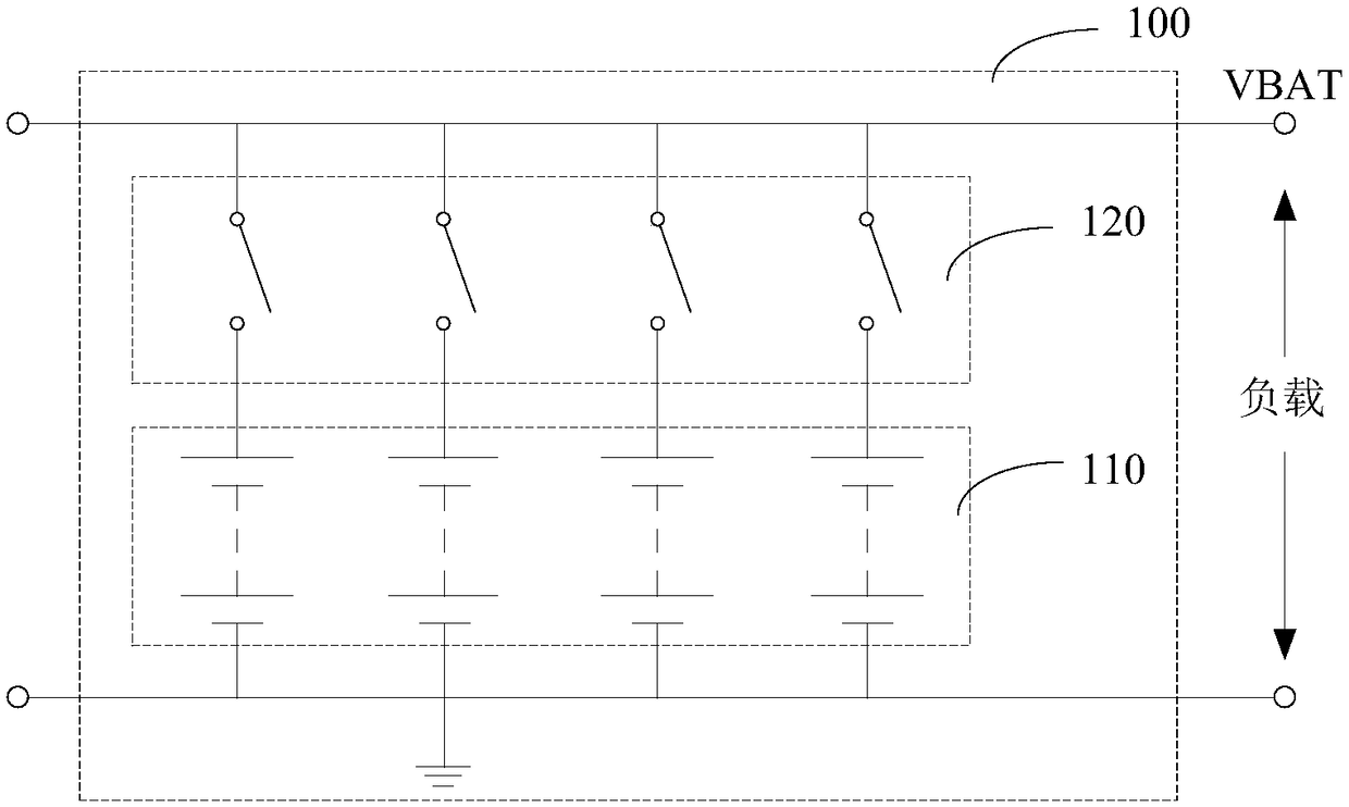
[0002] General electronic equipment is mainly powered by a single battery, its capacity is limited, and the usage scenarios are limited; when dual batteries are used for power supply, due to the different capacities of the primary and secondary batteries, there are significant differences in the discharge characteristics of the batteries; in the switching control process of the primary and secondary batteries In the middle, it is easy to cause the system to power down
When the main battery and the secondary battery supply power to the system at the same time, there is a mutual charging and discharging process between the two batteries, especially when one of the batteries fails, it will seriously affect the life of the battery and the performance of the system

Method used


Image

  • Multi-battery switching method, power supply device, and electronic equipment
  • Multi-battery switching method, power supply device, and electronic equipment
  • Multi-battery switching method, power supply device, and electronic equipment

Examples


Embodiment Construction

[0028] In order to make the purpose, technical solution and advantages of the present application clearer, the present application will be further described in detail below in conjunction with the accompanying drawings and embodiments. It should be understood that the specific embodiments described here are only used to explain the present application, and are not intended to limit the present application.

[0029] It can be understood that the terms "first", "second" and the like used in this application may be used to describe various elements herein, but these elements are not limited by these terms. These terms are only used to distinguish one element from another element. For example, a first battery unit could be termed a second battery unit, and, similarly, a second battery unit could be termed a first battery unit, without departing from the scope of the present application. Both the first battery cell and the second battery cell are battery cells, but they are not th...


PUM


Abstract

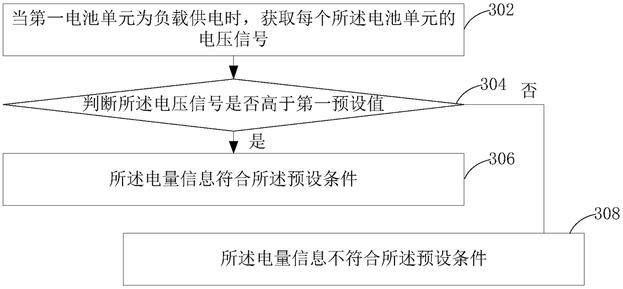
The embodiment of the application provides a multi-battery switching method, a power supply device, and electronic equipment. The method comprises the following steps: acquiring electric quantity information of each battery unit when the power supply device supplies power for the load; screening any battery unit with electric quantity information meeting the preset condition from unloaded batteryunits as the second battery unit when the electric quantity information of the first battery unit does not meet the preset condition, wherein the first battery unit is the battery unit for supplying power for the load at present; respectively outputting a control instruction to a first switch unit connected with the first battery unit and a second switch unit connected with the second battery unit, thereby controlling the on-off of the first switch unit and the second switch unit, and enabling the second battery unit to supply power for the load. The switching among multiple battery units canbe controlled, the independent power supply of each battery unit is realized; and meanwhile, multiple battery units are provided, the battery capacity is increased, and the cruising and use time is improved.

Description

technical field [0001] The present application relates to the technical field of charge and discharge, in particular to a multi-battery switching method, a power supply device, and electronic equipment. Background technique [0002] General electronic equipment is mainly powered by a single battery, its capacity is limited, and the usage scenarios are limited; when dual batteries are used for power supply, due to the different capacities of the primary and secondary batteries, there are significant differences in the discharge characteristics of the batteries; in the switching control process of the primary and secondary batteries In the middle, it is easy to cause the system to be powered off. When the main battery and the secondary battery supply power to the system at the same time, there is a mutual charging and discharging process between the two batteries, especially when one of the batteries fails, it will seriously affect the life of the battery and the performance o...

Claims


Application Information

Patent Timeline
IPC IPC(8): H02J7/00
CPCH02J7/0024
Inventor 张洲川
Owner OPPO CHONGQING INTELLIGENT TECH CO LTD
Why Eureka
Eureka Blog
Learn More