Expressway Toll System Based on Wireless Network Technology

A wireless network and expressway technology, applied in closed-circuit television systems, transmission systems, data exchange networks, etc., can solve the problems of separate laying of data and signal cables and high difficulty

Active Publication Date: 2021-03-02
SHANDONG HI SPEED COMPANY
View PDF5 Cites 0 Cited by
  • Summary
  • Abstract
  • Description
  • Claims
  • Application Information

AI Technical Summary

Problems solved by technology

It is more and more difficult to control signal interference by concentrating a large number of signal lines on the position of the driveway machine and industrial computer. The cables can still be reduced by using common wires, but the data and signal cables must be laid separately in order to avoid mutual interference.

Method used


Image

  • Expressway Toll System Based on Wireless Network Technology
  • Expressway Toll System Based on Wireless Network Technology
  • Expressway Toll System Based on Wireless Network Technology

Examples


Embodiment 1

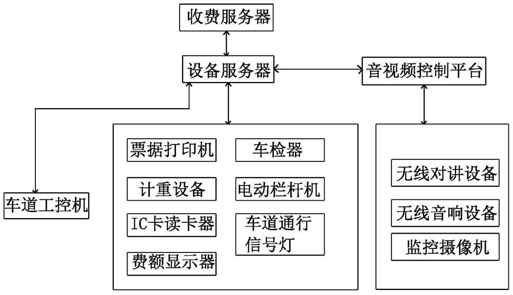
[0073] like figure 1 Shown, the expressway toll system based on wireless network technology of the present invention includes:

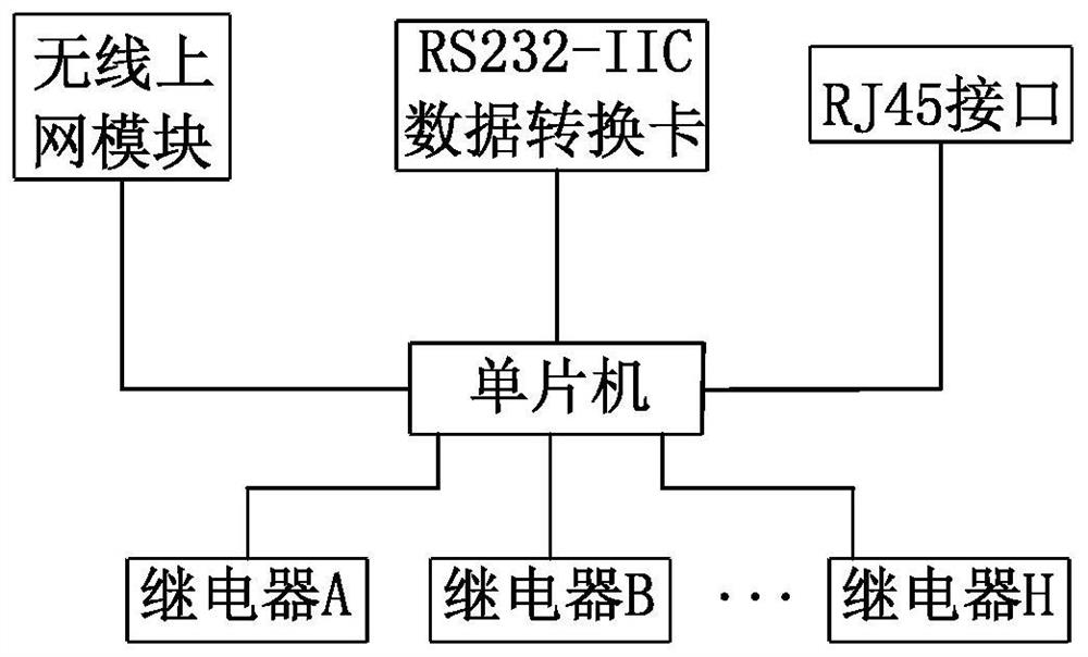
[0074] Driveway external equipment, each lane is equipped with a set of driveway external equipment, a set of driveway external equipment contains multiple external sub-equipment, the external sub-equipment mainly includes bill printers, weighing equipment, vehicle detectors, IC card readers, electric railings machine, toll display and lane traffic lights, equipped with a wireless conversion device for each external sub-equipment;

[0075] Driveway audio and video equipment, each lane is equipped with a set of audio and video equipment, mainly including wireless intercom equipment, wireless audio equipment and monitoring cameras, and the monitoring cameras are also equipped with a wireless conversion device;

[0076] The equipment server, the data communication between the external sub-equipment and the equipment server is realized by the wireless c...

Embodiment 2

[0115] This embodiment sets the disaster reduction mode on the basis of Embodiment 1. Specifically, the device server includes a main machine and an auxiliary machine, and the data received by the equipment server is transmitted to the charging server for backup in real time. Once the main machine fails, the auxiliary machine starts at the same time.

[0116] The switching strategy of the auxiliary machine is:

[0117] In the first step, the auxiliary machine receives the real-time data of the external equipment of the lane and the audio and video equipment of the lane from the toll server;

[0118] In the second step, the auxiliary machine checks whether the external equipment of the lane, the audio and video equipment of the lane, the industrial computer of the lane and the toll server are online. work on behalf of the host;

[0119] In the third step, the auxiliary machine reports the failure information of the main machine to the staff.

[0120] The driveway industrial c...


PUM


Abstract

The present invention relates to a highway toll system, in particular to a highway toll system based on wireless network technology, including lane audio and video equipment; lane external equipment, each set of lane external equipment includes a plurality of external sub-equipment; equipment server, composed of The wireless conversion device realizes the data communication between the external sub-equipment and the equipment server, and the audio and video equipment of the lane communicates with the equipment server through the audio and video control platform; the lane industrial computer, each lane industrial computer receives the external sub-equipment data of the corresponding lane through the equipment server; The charging server obtains the charging data and the operation status of the external equipment of the lane, and sends the charging data to the industrial computer of the lane. In the present invention, the control and data information of each lane equipment directly communicates with the equipment server through the wireless network, and the industrial computer of each lane is changed from the original basic control and data interaction center to a simple operation client, without laying a large number of lines and avoiding signal interference. Troubleshooting is quick.

Description

technical field [0001] The invention relates to a highway toll system, in particular to a highway toll system based on wireless network technology. Background technique [0002] The toll collection system of the high-speed toll station is mainly composed of toll server, lane equipment, network equipment and so on. Among them, the lane equipment includes: lane control machine (referred to as lane machine), lane control computer (referred to as industrial computer), lane traffic lights, license plate recognition, lane cameras and cameras in sentry boxes, voice quotes, computer monitors, IC card readers , Electric railing machine, bill printer, vehicle inspection device, weighing equipment, character stacker, fee display, toll keyboard and other equipment; network equipment mainly includes: optical transmission equipment, network cable transmission, video transmission, etc. [0003] Lane equipment is the main realization of charging activities. The lane control computer is mai...

Claims


Application Information

Patent Timeline
Patent Type & Authority Patents(China)
IPC IPC(8): G07B15/06H04L12/24H04L12/28H04L29/08H04N7/18
CPCG07B15/063H04L12/2869H04L41/0663H04L67/12H04L67/125H04N7/183
Inventor 陈善智李志强
Owner SHANDONG HI SPEED COMPANY
Why Eureka
Try Eureka