
A bms AC charging process simulation test equipment

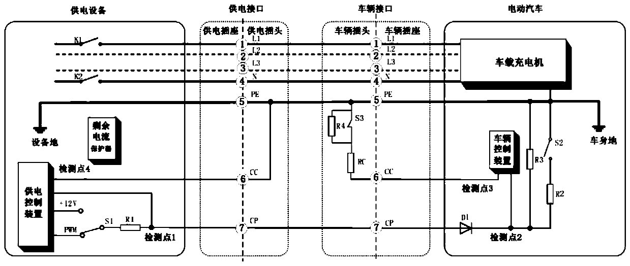
A technology of AC charging and process simulation, applied in the direction of measuring electricity, measuring devices, measuring electrical variables, etc., can solve the problems of high cost, long time consumption, and a large amount of test time spent waiting for the battery to be fully charged.

Active Publication Date: 2020-08-04
VKAN CERTIFICATION & TESTING
View PDF10 Cites 0 Cited by
  • Summary
  • Abstract
  • Description
  • Claims
  • Application Information

AI Technical Summary

Problems solved by technology

Compared with the first method, the second method saves the entire electric vehicle, and only uses the on-board charger to play the same role, so the system construction cost is reduced, but it still involves the purchase of charging piles and other equipment. The overall cost of the system is still high
[0008] 1. Time-consuming
[0009] The above two methods are to wait for the battery to be fully charged. After the BMS detects that the battery is fully charged, it uploads the CAN message "Battery is full". For general AC charging piles, this process takes more than 8 hours
[0010] 2. It is inconvenient to locate the test problem
[0011] Locating test problems requires repeated disassembly and assembly of the battery pack to take out the BMS for rectification verification, and the process of disassembling the battery pack is cumbersome and time-consuming
[0012] 3. Incomplete testing
[0013] In the development and design of BMS, it is necessary to match all types of AC charging piles that meet the requirements of the new national standard, such as AC charging piles with different cable capacities. However, due to the low efficiency of the existing test methods, only one charging pile is generally tested. Conduct tests on charging piles connected to different cable capacities

Method used


Image

  • A bms AC charging process simulation test equipment
  • A bms AC charging process simulation test equipment
  • A bms AC charging process simulation test equipment

Examples


Embodiment Construction

[0088] Figure 4 It is the simulation test equipment for the BMS AC charging process of this embodiment (hereinafter referred to as the equipment of this embodiment, that is, Figure 4 The analog device in ), when the interface is docked with the BMS connector, the schematic diagram of the circuit connection relationship with the BMS. In this embodiment, a PC is used as a display module, and the device in this embodiment is connected to the PC through its UART terminal. After docking the device interface of this embodiment with the BMS connector, it is realized Figure 4 The docking relationship between the simulated device and the BMS. Figure 4 The PWR_CTRL, CAN, CC, and CP of the simulated device in the interface represent the pins connected to the BMS power supply circuit, CAN signal transceiver circuit, CC signal circuit, and CP signal circuit in the interface, and the POWER, CAN, CC, and CP of the BMS represent the BMS respectively. Power input pins, CAN communication...


PUM


Abstract

The invention relates to equipment for simulating interaction between an AC charging pile, a vehicle-mounted charger and a BMS to realize the charging process test. The equipment is composed of a power supply module, a control module, a display module, a CAN signal transmit-receive circuit, a display module connection circuit, a BMS power supply circuit, a CC signal circuit, a CP signal circuit, aCP signal feedback circuit and an interface used for being butted with the BMS connector. After the BMS is connected and the test is started, the equipment can simulate the interaction mode between the AC charging pile, the vehicle-mounted charger and the BMS in the electric automobile AC charging process so as to perform the AC charging process test on the BMS. With application of the equipmentfor performing the BMS test, the development test cost of the BMS can be greatly reduced, and high voltage is not involved in the test system so as to be safer and more reliable.

Description

technical field [0001] Based on the AC charging national standard GB / T 18487.1-2015 (hereinafter referred to as the new national standard), the present invention provides a BMS AC charging process simulation test equipment. Background technique [0002] With the development and popularization of electric vehicles, the country has promulgated the national standard for AC charging and enforced it as a new energy vehicle access regulation. Corresponding to the development and testing process of BMS, it is necessary to invent a test equipment that simulates AC charging piles and The method meets the control requirements of the new national standard. Before the development of BMS (abbreviation of BATTERY MANAGEMENT SYSTEM, which is a combination of software and hardware) is completed and loaded into the power battery pack, a simulated AC charging process test is carried out. Avoid the possibility of subsequent unpacking or even vehicle rectification of the BMS due to abnormal AC ...

Claims


Application Information

Patent Timeline
Patent Type & Authority Patents(China)
IPC IPC(8): G01R31/00
CPCG01R31/00
Inventor 张仕彬魏国华黄鲲邓俊泳
Owner VKAN CERTIFICATION & TESTING
Learn More