
A radial well guiding plugging agent injection oil well water plugging method

A technology for oil well water plugging and radial wells, which is applied in wellbore/well components, earthwork drilling, sealing/isolation, etc. It can solve the problems of increasing operation difficulty and cost, high injection pressure, and inability of plugging agents to enter

Active Publication Date: 2020-06-02
CHINA UNIV OF PETROLEUM (EAST CHINA)
View PDF5 Cites 0 Cited by
  • Summary
  • Abstract
  • Description
  • Claims
  • Application Information

AI Technical Summary

Problems solved by technology

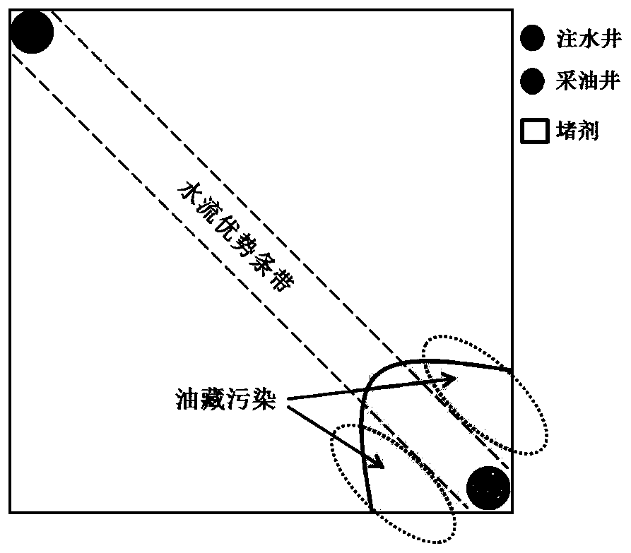
However, the plugging agent will inevitably enter the surrounding low-permeability formations, causing reservoir pollution (such as figure 2 shown)
Improper handling will even block the oil well, requiring subsequent complicated processes such as plugging removal, which will increase the difficulty and cost of the operation
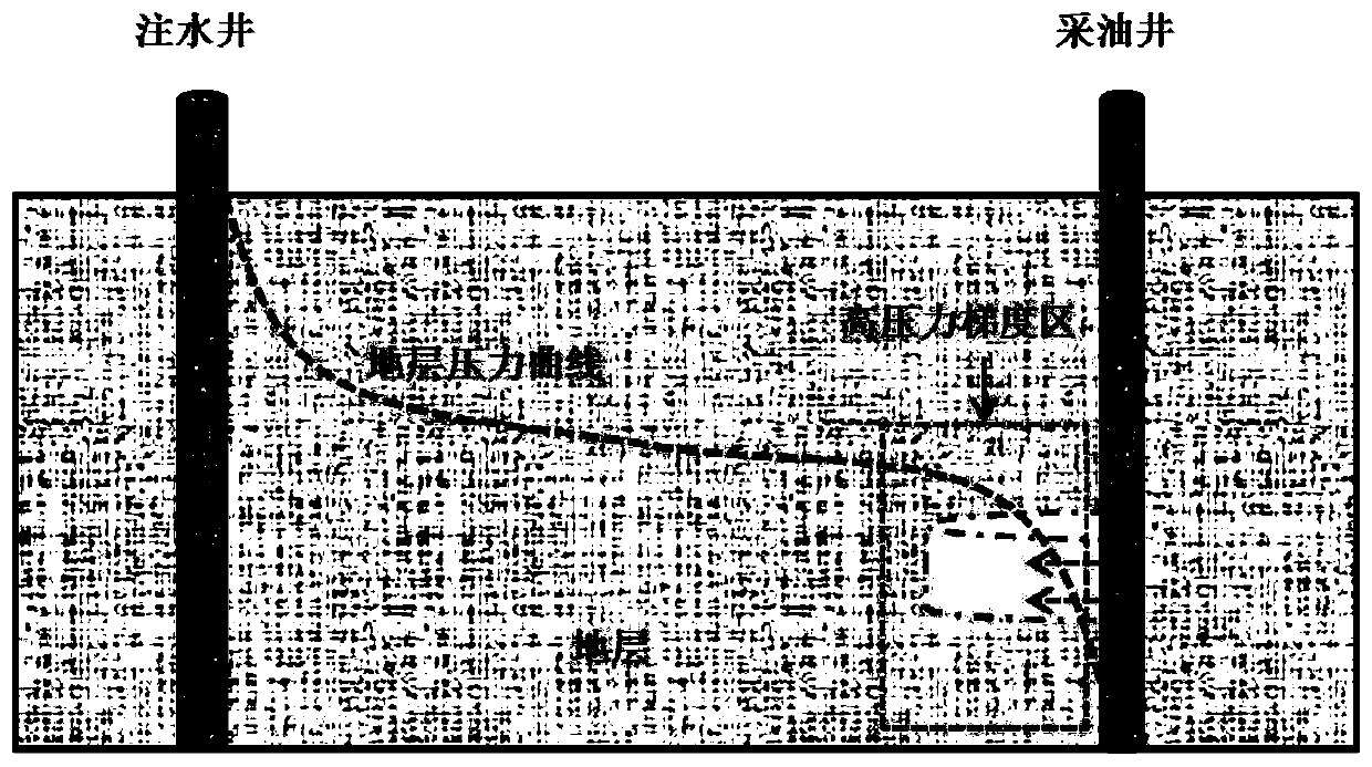
[0006] In addition, due to the large formation pressure gradient near the oil well, problems such as high injection pressure and low injection volume of plugging agent are faced during general injection (such as image 3 shown)
As a result, the plugging agent cannot enter the deep part of the formation, and it is difficult to form a plugging with sufficient strength when injecting the plugging agent. If the injection pressure is increased blindly, it will intensify the entry of the plugging agent into the low-permeability formation and pollute the reservoir.
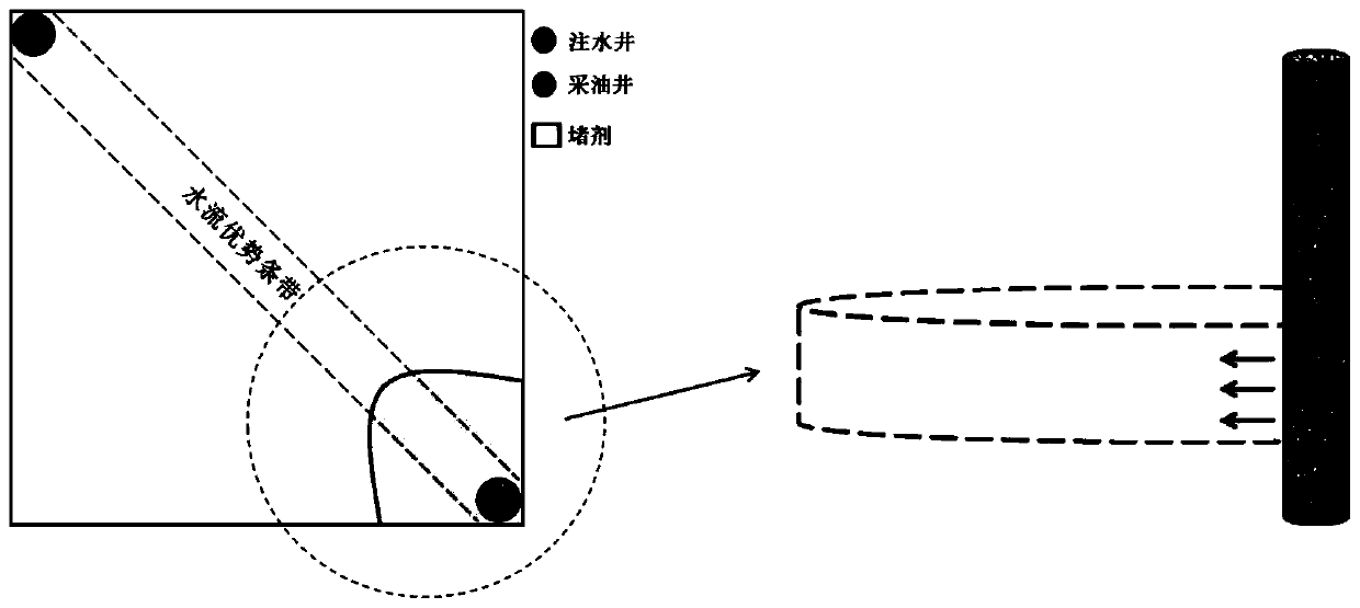
[0007] Generally speaking, the general injection of plugging agent is mostly used for water plugging in oil wells at present. The general injection method has the following disadvantages: ①The plugging agent seeps radially toward the formation with the wellbore as the center, and it cannot realize precise injection of plugging agent in the dominant water flow zone ; ② The plugging agent will enter the low permeability formation and pollute the reservoir; ③ The pressure gradient of the formation near the oil well is large, resulting in a high injection pressure of the plugging agent, and it is difficult for the plugging agent to enter the deep formation; ④ Due to the short gelation time of the plugging agent, the injection pressure is high As a result, the amount of plugging agent injected in a short period of time is small, and it is difficult to form a plugging with sufficient strength

Method used


Image

  • A radial well guiding plugging agent injection oil well water plugging method
  • A radial well guiding plugging agent injection oil well water plugging method
  • A radial well guiding plugging agent injection oil well water plugging method

Examples


Embodiment Construction

[0079] Below in conjunction with accompanying drawing and specific embodiment the present invention is described in further detail:

[0080] 1. Method description

[0081] (1) Determination of radial well orientation

[0082] Using engineering methods (tracer method, PI isovalue map description method, log curve characteristic ratio judgment method, etc.) to determine the orientation of the dominant water flow zone in the formation, the orientation of the radial well is consistent with the orientation of the dominant water flow zone.

[0083] (2) Determination of radial well length

[0084] The pressure distribution in the formation shows the characteristics of large pressure gradient between water injection well and oil production well, and small pressure gradient in the deep formation (such as Figure 4 shown). The strength of the plugging agent selected for oil well water plugging must at least be able to withstand the pressure gradient of the formation around the oil we...


PUM


Abstract

The invention discloses a method for guiding plugging agents into an oil well for water plugging by radial wells, and belongs to the field of oil production engineering in oil development. The methodcomprises the following step that the orientation of the radial wells, the length of the radial wells, numbers of the radial wells, dosage of the plugging agents and injection displacement are determined. The method for guiding the plugging agents into the oil well for water plugging by the radial wells changes the flow line of the plugging agents along a producing well as radial flow in a traditional general injection method to the radial flow along the radial wells in a flow advantage band, the precise delivery of the plugging agents is realized, and the damage to an oil reservoir is reduced. The radial wells have high flow conductivity and can be regarded as pipe flow, compared with the formation seepage flow, the injection pressure to the depth of the formation is greatly reduced, andthe effects of decompression and increasing injection are achieved. The method for guiding the plugging agents into the oil well for water plugging by the radial wells can realize the precise deliveryof the plugging agents in the flow advantage band and the decompression and increasing injection, and is of great significance for improving the water plugging effect of the oil well.

Description

technical field [0001] The invention belongs to the field of oil production engineering in petroleum development, and in particular relates to a water shutoff method for radial well guiding plugging agent injection into oil wells with the functions of precise injection and depressurization and injection enhancement. Background technique [0002] Reservoir water injection development is the main means of secondary oil recovery. Water injection into the formation through water wells can maintain reservoir pressure, and at the same time, injecting water as a displacement fluid can displace crude oil in the formation from deep formations into oil wells, improving oil recovery. . [0003] Studies have shown that long-term water injection development will change the pore structure of formation rocks, increase permeability, and form water flow dominant bands. The line between the injection and production wells is the shortest, the pressure gradient is the largest, and the water fl...

Claims


Application Information

Patent Timeline
Patent Type & Authority Patents(China)
IPC IPC(8): E21B33/138E21B49/00
CPCE21B33/138E21B49/00
Inventor 刘晓强曲占庆郭天魁王东英叶卫保马中跃温鸿滨李云龙崔旭瑶郝童王晓之
Owner CHINA UNIV OF PETROLEUM (EAST CHINA)
Learn More