


Quick Research
Generate reliable direction feasibility study reports for your R&D in just a few steps.

Technical Q&A
Discover and master advanced knowledge NOW. Basics, ideas, possibilities, all at once.

Find Solutions
As an expert in R&D theories, this can generate solutions to your technical problems instantly.

Evaluate Feasibility
Analyze your overall solution with one click, know your potential R&D risks in advance.

Monitor Landscape
Get weekly tech updates, stay abreast of the latest tech innovations and key insights.
Spinning-drawing combined machine and monomer suction device for spinning machine
A technology of spinning device and suction device, which is applied in the field of spinning-drawing combined machine and monomer suction device for spinning machine, which can solve the problems of many broken ends and affecting product quality, etc.
- Summary
- Abstract
- Description
- Claims
- Application Information
AI Technical Summary
Problems solved by technology
Method used
Image

Examples
Embodiment 1
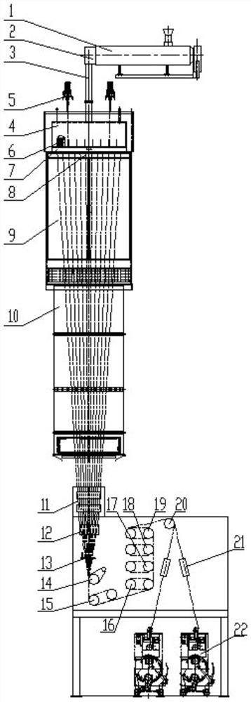
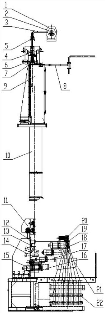
[0070] see figure 1 and figure 2 , a combined spinning and drawing machine, including an extrusion device, a melt piping system 3, a metering pump 5, a spinning device, a monomer suction device 8, a cooling device, a tunnel part 10, an upper Oil device 11, guide wire drafting device and winding device 22. The monomer suction device 8 is arranged at the wire feeding end of the cooling device, and the monomer suction part 8 includes a suction pipe 8a, a spray device 8b and a spray adsorption area 8c, and the suction pipe 8a is arranged at the wire feeding end of the cooling device, and the suction pipe 8a is arranged at the wire feeding end of the cooling device. The suction inlet of the suction pipe 8a is opposite to the wire outlet end of the annealer part 7, the suction outlet 8i communicates with the spray adsorption area 8c, and the injection device 8b is installed in the injection adsorption area 8c, and its installation height is higher than the suction outlet 8i The f...
Embodiment 2
[0113] A monomer suction device for spinning machine, see Figure 8 , comprising a suction pipe 8a, a spray device 8b and a spray adsorption zone 8c, wherein:
[0114] The suction inlet of the suction pipe 8a communicates with the tow channel of the spinning machine, specifically the cooling channel of the cooling device of the spinning machine, and extracts the gaseous monomers and oligomers before they enter the cooling device to solve the cooling problem. For the problem of monomer crystallization on the air outlet of the device, the suction outlet 8i of the suction pipe 8a communicates with the jet adsorption area 8c.
[0115] see Figure 9 , the suction inlet of the suction pipe 8a is a cavity 8d with decreasing width, the widest part (opening) joins with the cooling device, and the two are equal in width, and the wire feeding end of the cooling device is completely covered along the width direction. The cavity 8d is provided with a monomer heating device 8e. In this em...
Embodiment 3
[0120] A monomer suction device for spinning machine, see Figure 11 , comprising a suction pipe 8a, a spray device 8b and a spray adsorption zone 8c, wherein:
[0121] The suction inlet of the suction pipe 8a communicates with the tow channel of the spinning machine, specifically the cooling channel of the cooling device of the spinning machine, and extracts the gaseous monomers and oligomers before they enter the cooling device to solve the cooling problem. For the problem of monomer crystallization on the air outlet of the device, the suction outlet 8i of the suction pipe 8a communicates with the jet adsorption area 8c.
[0122] see Figure 12 , the suction inlet of the suction pipe 8a is a cavity 8d with decreasing width, the widest part (opening) joins with the cooling device, and the two are equal in width, and the wire feeding end of the cooling device is completely covered along the width direction. A monomer heating device 8e is provided in the cavity 8d, and the mo...
PUM
| Property | Measurement | Unit |
|---|---|---|
| Melting point | aaaaa | aaaaa |
| Glass transition temperature | aaaaa | aaaaa |
| Breaking strength | aaaaa | aaaaa |
Abstract
Description
Claims
Application Information
 - R&D Engineer
- R&D Manager
- IP Professional
- Industry Leading Data Capabilities
- Powerful AI technology
- Patent DNA Extraction
Browse by: Latest US Patents, China's latest patents, Technical Efficacy Thesaurus, Application Domain, Technology Topic, Popular Technical Reports.
© 2024 PatSnap. All rights reserved.Legal|Privacy policy|Modern Slavery Act Transparency Statement|Sitemap|About US| Contact US: help@patsnap.com