
Sea tying carrying pole device and sea tying method for heavy equipment

A technology of heavy equipment and shoulder poles, which is applied to the device for preventing multi-way movement of goods, load handling device, transportation and packaging, etc. It can solve the problems of high transportation cost, great influence of lashing operations, and long operation cycle, etc., to achieve guaranteed reliability. Ease of dismantling, avoiding difficulties in lifting and installation, saving cost and time

Active Publication Date: 2018-10-12
HUADIAN CAOFEIDIAN HEAVY IND
View PDF7 Cites 1 Cited by
  • Summary
  • Abstract
  • Description
  • Claims
  • Application Information

AI Technical Summary

Problems solved by technology

[0003] In the past, this kind of lashing method was to weld the oblique support directly to the leg support position of the equipment when loading the ship, and cut it when unloading the ship. This is a kind of secondary damage to the equipment and the tooling used for lashing cannot be used. It is reused for a long time, and it has high requirements on the stable state of the transport ship during the operation process, and the operating environment has a great impact on the lashing operation
The traditional lashing and fixing method results in high transportation costs, long lashing operation cycle for heavy equipment, and due to the lashing method, there is a large stress concentration problem. During water transportation, due to the swing of the transport ship, it is easy to cause partial lashing failure. , there is a great security risk

Method used


Image

  • Sea tying carrying pole device and sea tying method for heavy equipment
  • Sea tying carrying pole device and sea tying method for heavy equipment
  • Sea tying carrying pole device and sea tying method for heavy equipment

Examples


Embodiment Construction

[0035] The specific implementation manners of the present invention will be described in detail below in conjunction with the accompanying drawings.

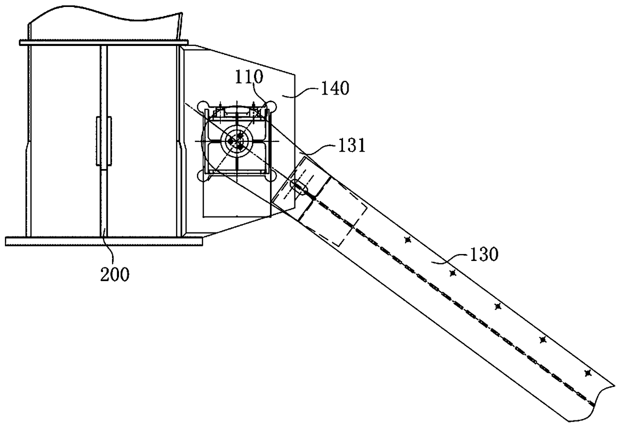
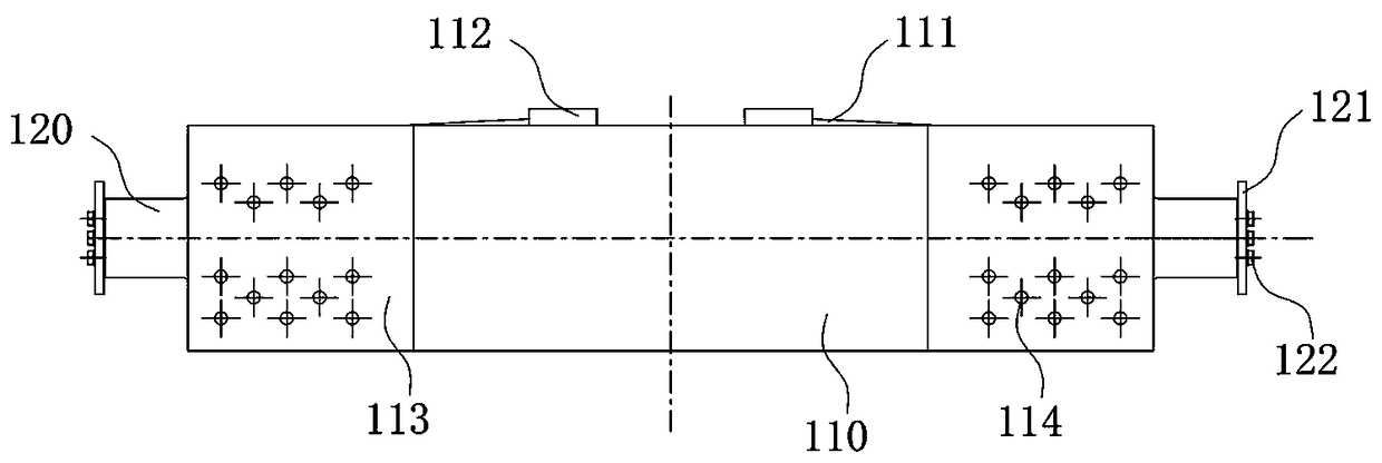
[0036] see Figure 1-Figure 7 , the present invention is a sea-tied shoulder pole device for heavy equipment, comprising a shoulder pole main body 110, a pin shaft 120 and a support beam 130, the pin shaft 120 is matched and arranged in the shoulder pole main body 110, and the end of the pin shaft 120 extends out of the shoulder pole main body 110; The upper end of the support beam 130 is matched and sleeved on the end of the pin shaft 120, and both ends of the pin shaft 120 are provided with a shaft end limit assembly. The shaft end limit assembly and the main body of the shoulder pole limit the lateral sliding movement of the support beam. The shaft end limit assembly in the example is an end cover 121 fixedly arranged at the end of the pin shaft. The end cover 121 and the pin shaft 120 are fixedly connected by bolts 122, and ...


PUM


Abstract

The invention belongs to the technical field of waterway transportation of heavy equipment, and discloses a sea tying carrying pole device and a sea tying method for the heavy equipment. The sea tyingcarrying pole device comprises a carrying pole body, a hinge pin and supporting beams, wherein the hinge pin is disposed in the carrying pole body in a matched mode, and the end portion of the hingepin extends out of the carrying pole body. The upper ends of the supporting beams are arranged at the end portion of the hinge pin in a sleeving mode, and shaft end limiting assemblies are disposed atboth ends of the hinge pin. The shaft end limit assemblies and the carrying pole body limit the lateral sliding movement of the supporting beams. The sea tying carrying pole device realizes the modular design and standardized design of heavy equipment water transportation, and realizes the structural design of the sea tying carrying pole device for the heavy equipment and the characteristic property of the transport ship water transportation; targeted design is carried out from installation and disassembly, operation and construction, bearing performance and the like, and at the same time, the recycling and construction cost of the sea tying carrying pole device are considered and optimized, and breakthrough innovation in the whole equipment and construction method is achieved.

Description

technical field [0001] The invention belongs to the technical field of water transportation of heavy equipment, and in particular relates to a sea-tied pole device and a sea-tied method for heavy equipment. Background technique [0002] Transporting rail-mounted heavy equipment by water is a very dangerous and difficult task. The difficulties and dangers mainly exist in the process of water transport. If the equipment is not firmly tied to the transport ship, it will cause serious damage to the equipment, transport ships and personnel. danger. In order to overcome the above difficulties, reduce risks, reduce operating time, and save costs, it will be a trend to tie rail-mounted heavy equipment firmly to transport ships and form a corresponding standard model. [0003] In the past, this kind of lashing method was to weld the oblique support directly to the leg support position of the equipment when loading the ship, and cut it when unloading the ship. This is a kind of secon...

Claims


Application Information

Patent Timeline
IPC IPC(8): B63B25/24B63B25/00
CPCB63B25/00B63B25/24
Inventor 邰运辉孙建广任改运安福新张晶心李忠明纪雪林
Owner HUADIAN CAOFEIDIAN HEAVY IND
Learn More