
High-strength bumper for new energy car

A new energy vehicle, high-strength technology, applied in bumpers, vehicle parts, vehicle safety arrangements, etc., can solve the problems of maintenance personnel's workload, long disassembly time, and inconvenient disassembly, and achieves short disassembly time, simple structure, and convenience. The effect of disassembly

Active Publication Date: 2018-10-12
HEFEI DONGSHENG AUTO PARTS CO LTD
View PDF6 Cites 2 Cited by
  • Summary
  • Abstract
  • Description
  • Claims
  • Application Information

AI Technical Summary

Problems solved by technology

[0002] The car bumper is a safety device that absorbs and slows down the external impact and protects the front and rear of the car body. Many years ago, the front and rear bumpers of the car were stamped with steel plates into channel steel, riveted or welded with the frame longitudinal beam, and have a section with the car body. Large gaps, although high in strength, look very unattractive. With the development of the automobile industry and the extensive application of engineering plastics in the automobile industry, automobile bumpers, as an important safety device, are also on the road to innovation. In addition to maintaining the original protection function, the front and rear bumpers of today's cars also need to pursue harmony and unity with the car body shape, and pursue their own lightweight
[0003] The current car bumper is extremely inconvenient to disassemble during the replacement process, which brings a great workload to the maintenance personnel, and the disassembly time is long and the efficiency is low. Therefore, we propose a high-strength bumper for new energy vehicles. to solve the above-mentioned problems

Method used


Image

  • High-strength bumper for new energy car
  • High-strength bumper for new energy car
  • High-strength bumper for new energy car

Examples


Embodiment Construction

[0018] The following will clearly and completely describe the technical solutions in the embodiments of the present invention with reference to the accompanying drawings in the embodiments of the present invention. Obviously, the described embodiments are only some, not all, embodiments of the present invention.

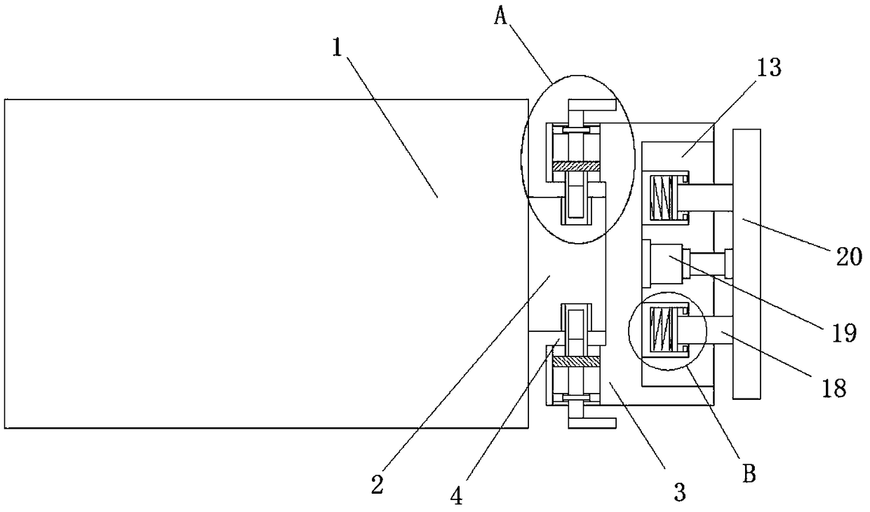
[0019] refer to Figure 1-3 , a high-strength bumper for new energy vehicles, comprising a car body 1, a mounting plate 2 is fixedly installed on one side of the car body 1, a bumper body 3 is provided on one side of the mounting plate 2, and a bumper body 3 is installed on one side A mounting groove 4 is provided, and the mounting plate 2 extends into the mounting groove 4 away from the side of the car body 1. The top and bottom of the mounting plate 2 are provided with a fixing groove 5, and the top inner wall and the bottom inner wall of the mounting groove 4 are provided with fixing grooves. The hole 6 is slidingly connected to the side wall of the fixed hole 6 w...


PUM


Abstract

The invention discloses a high-strength bumper for a new energy car. The high-strength bumper comprises a car body. A mounting plate is fixedly mounted on one side of the car body. A bumper body is arranged on one side of the mounting plate. A mounting groove is formed in one side of the bumper body. The side, away from the car body, of the mounting plate extends into the mounting groove. Fixing grooves are formed in the top and the bottom of the mounting plate correspondingly. Fixing holes are formed in the top inner wall and the bottom inner wall of the mounting groove correspondingly. Moving plates are slidably connected to the side walls of the fixing holes. Fixing shafts are welded to the bottoms of the moving plates. The bottoms of the fixing shafts extend into the fixing grooves. Rotating grooves are formed in the tops of the fixing shafts. The high-strength bumper is simple in structure, the bumper body can be protected by an anti-collision plate, damage to the bumper body dueto direct collision is prevented, the bumper body can be easily dismounted by rotating a rotating shaft, the dismounting time is short, the efficiency is high, and using is convenient and fast.

Description

technical field [0001] The invention relates to the technical field of automobile manufacturing, in particular to a high-strength bumper for new energy automobiles. Background technique [0002] The car bumper is a safety device that absorbs and slows down the external impact and protects the front and rear of the car body. Many years ago, the front and rear bumpers of the car were stamped with steel plates into channel steel, riveted or welded with the frame longitudinal beam, and have a section with the car body. Larger gaps, although high in strength, look very unattractive. With the development of the automobile industry and the extensive application of engineering plastics in the automobile industry, automobile bumpers, as an important safety device, are also on the road to innovation. In addition to maintaining the original protection function, the front and rear bumpers of today's cars also pursue harmony and unity with the car body shape, and pursue their own lightwe...

Claims


Application Information

Patent Timeline
Patent Type & Authority Applications(China)
IPC IPC(8): B60R19/36
CPCB60R19/023B60R19/36B60R2019/247
Inventor 宗芳
Owner HEFEI DONGSHENG AUTO PARTS CO LTD
Learn More