Multilevel inverter

A technology of inverters and capacitors, applied in the field of multi-level inverters, can solve the problems of limited availability of power components withstanding voltage, reduced winding insulation life, unfavorable number and complexity of control device components, etc.

Inactive Publication Date: 2018-10-09
伟肯有限公司
View PDF5 Cites 4 Cited by
  • Summary
  • Abstract
  • Description
  • Claims
  • Application Information

AI Technical Summary

Problems solved by technology

[0005] The disadvantage of the known topology is e.g. especially due to the high voltage steps of the NPC with 3-level output voltage, which tends to generate harmful overvoltage spikes at the motor end of long cables, reducing the life of the winding insulation
With some topologies, the voltage withstand capability of the power components limits the availability
In addition, with MMC and CHB, from a system cost standpoint, the part count and complexity of the controls can be detrimental

Method used


Image

  • Multilevel inverter
  • Multilevel inverter
  • Multilevel inverter

Examples


Embodiment Construction

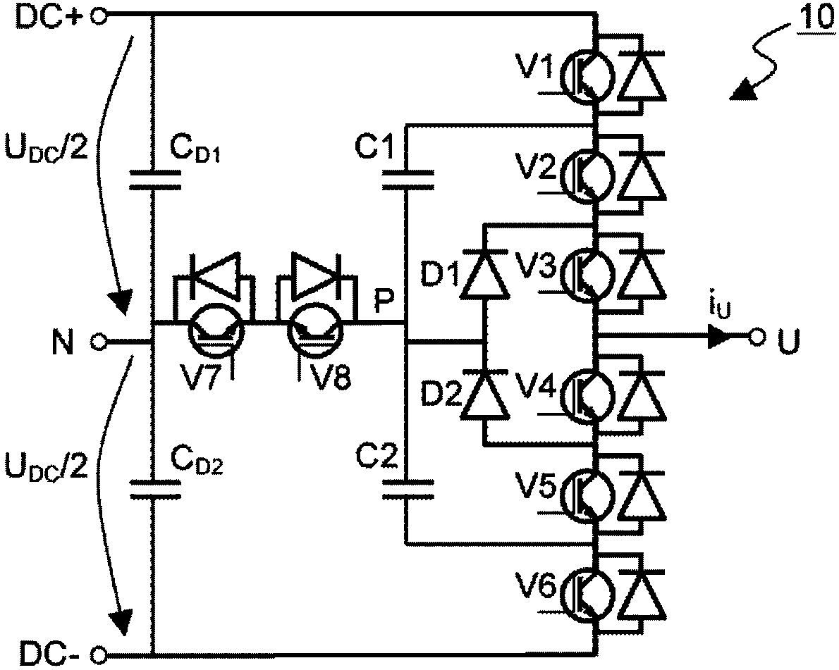
[0025] figure 1 A schematic diagram of an inverter circuit 10 according to the invention is shown. It should be noted that this figure has been simplified to focus on elements relevant to a clear understanding of the present invention, while other elements have been omitted for the sake of clarity, such as identification marks of some components, control arrangements of controllable components, etc., which are of great importance to the present invention. obvious to those of ordinary skill in the art.

[0026] The inverter circuit is connected through three power nodes DC+, N and DC- to have two substantially equal voltage levels U DC / 2 external two-level DC voltage link. The DC+ node is connected to the positive pole, the DC node is connected to the negative pole, and the N node is connected to the midpoint of the DC link voltage. The output node U of the inverter circuit is connected to a load. The DC voltage across nodes DC+ and DC- can be provided by rectifying the AC...


PUM


Abstract

An inverter circuit, coupled to a two-level DC voltage supply and being able to form a five-level output voltage is described, together with a method for operating the inverter circuit. The inverter circuit comprises a series connection of six unidirectional power semiconductor switches, each coupled to an antiparallel diode, between the positive and negative nodes of the supplying DC voltage. Theinverter circuit further comprises a series connection of two internal capacitors between the cathodes of the first and the fifth switches of the series connection, the connection point of the capacitors being coupled to the internal node of the inverter circuit. In use, the unidirectional power semiconductor switches are controlled in order to set the voltage of the output of the inverter circuit.

Description

technical field [0001] The present invention relates to multilevel inverters, for example multilevel inverters capable of generating five voltage levels. Background technique [0002] Inverters are widely used in power electronics applications that convert between direct current (DC) power and alternating current (AC) power. The most common type of inverter, a PWM inverter converts a DC voltage to an AC output voltage consisting of pulses with varying widths. The method of forming the output voltage is called pulse width modulation (PWM), and the purpose of output voltage formation is usually to produce a pulse pattern with a minimum content of desired fundamental components and undesired harmonics. [0003] At low voltages, such as grid voltages of less than 1 kV, the most common inverter type is the two-level inverter, with which the output voltage can only have the value of the positive or negative pole of the supplied DC voltage. At higher grid voltages, multilevel inv...

Claims


Application Information

Patent Timeline
IPC IPC(8): H02M7/483
CPCH02M7/483H02P27/14H02M7/487H02M1/0009H02M1/088H02M7/217H02P27/08
Inventor 朱哈马提·霍宁威廉·吉翁特
Owner 伟肯有限公司
Why Eureka
Try Eureka