A new energy vehicle motor housing circulating water channel sand core structure
What is Al technical title?
Al technical title is built by PatSnap Al team. It summarizes the technical point description of the patent document.
A technology of new energy vehicles and circulating water channels, which is applied in the direction of motors, electric vehicles, casings/covers/supports, etc., can solve the problems of low heat dissipation efficiency, affecting the stability of the motor, and the inability to realize the rapid heat dissipation function of the motor, etc., to achieve Fast-diffusing, fast-absorbing effect
Active Publication Date: 2020-04-28
东莞市伟源五金有限公司
View PDF4 Cites 0 Cited by
Summary
Abstract
Description
Claims
Application Information
AI Technical Summary
This helps you quickly interpret patents by identifying the three key elements:
Problems solved by technology
Method used
Benefits of technology
Problems solved by technology
[0002] The sand core structure of the circulating water channel of the motor shell in the prior art cannot realize the rapid positioning and fixing of the motor, and the installation stability of the motor is not good; the sand core structure of the circulating water channel of the motor shell in the prior art cannot realize the rapid heat dissipation function of the motor, The heat dissipation efficiency is not high, which affects the stability of the motor operation, so there is an urgent need for a new energy vehicle motor shell circulating waterway sand core structure to solve the above problems
Method used
Image
Click on the blue label to locate the original text in one second.
Reading with bidirectional positioning of images and text.
Examples
Embodiment Construction
[0019] In order to make the technical means, creative features, goals and effects achieved by the present invention easy to understand, the present invention will be further described below in conjunction with specific embodiments.
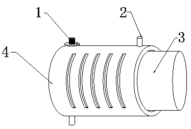
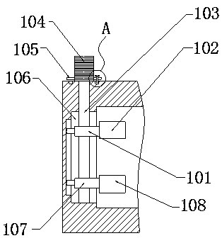
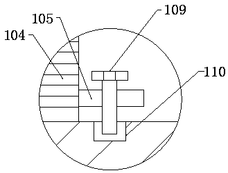
[0020] see Figure 1-Figure 4 , the present invention provides a technical solution: a new energy vehicle motor housing 4 circulating waterway sand core structure, including a motor body 3, a housing 4, a motor fixing mechanism 1 and a circulating waterway mechanism 2, the motor body 3 is assembled in the casing Inside the body 4, and the motor body 3 is connected with the casing 4 through the motor fixing mechanism 1, the motor fixing mechanism 1 is arranged on the left side of the casing 4, the motor fixing mechanism 1 includes an adjusting nut one 101, a pressing plate one 102, a two-way Screw rod 103, adjustment column 104, turntable 105, groove 106, adjustment nut 2 107, pressing plate 2 108, positioning bolt 109 and annular clamping groove 1...
PUM
Abstract
The invention provides a circulating water channel sand core structure for a novel energy automobile motor shell. The circulating water channel sand core structure comprises a motor body, a shell, a motor fixing mechanism and a circulating water channel mechanism, wherein the motor body is assembled in the shell, the motor body is connected with the shell through the motor fixing mechanism, the motor fixing mechanism is arranged on the left side surface of the shell; the motor fixing mechanism comprises a first adjusting nut, a first pressing plate, a two-way screw, an adjusting column, a rotating disc, a groove, a second adjusting nut, a second pressing plate, a positioning bolt and an annular clamping groove; the circulating water channel mechanism is arranged on the annular side surfaceof the shell; the circulating water channel mechanism comprises a support, a heat conduction aluminum rod, a heat dissipation fin, a heat dissipation hole, a water inlet pipe, a circulating water pipe, an upper spring, an upper clamping plate, a lower clamping plate, a lower spring and a drainage pipe. Compared with the prior art, the circulating water channel sand core structure has the following beneficial effects that the rapid positioning and fixing functions of a motor body are realized, and the rapid absorption and dispersion of the heat of the motor body are achieved.
Description
technical field [0001] The invention relates to a sand core structure of a circulating waterway for a new energy vehicle motor casing, and belongs to the technical field of new energy motor production. Background technique [0002] The sand core structure of the circulating water channel of the motor shell in the prior art cannot realize the rapid positioning and fixing of the motor, and the installation stability of the motor is not good; the sand core structure of the circulating water channel of the motor shell in the prior art cannot realize the rapid heat dissipation function of the motor, The heat dissipation efficiency is not high, which affects the stability of the motor operation, so there is an urgent need for a new energy vehicle motor housing circulating water channel sand core structure to solve the above problems. Contents of the invention [0003] Aiming at the deficiencies in the prior art, the purpose of the present invention is to provide a sand core stru...
Claims
Application Information
Patent Timeline
Application Date:The date an application was filed.
Publication Date:The date a patent or application was officially published.
First Publication Date:The earliest publication date of a patent with the same application number.
Issue Date:Publication date of the patent grant document.
PCT Entry Date:The Entry date of PCT National Phase.
Estimated Expiry Date:The statutory expiry date of a patent right according to the Patent Law, and it is the longest term of protection that the patent right can achieve without the termination of the patent right due to other reasons(Term extension factor has been taken into account ).
Invalid Date:Actual expiry date is based on effective date or publication date of legal transaction data of invalid patent.