
A direct-writing screen edge-banding plate-making machine and edge-banding method

A technology of screen plate making and direct writing, which is applied in the field of direct writing screen edge banding plate making machine and edge banding, which can solve the problems of reducing the overall plate making efficiency and increasing the workload of digital micromirror devices, so as to achieve rapid sealing Side plate making, shortening plate making time, and simple structure

Active Publication Date: 2020-08-21
北京弘浩千瑞科技有限公司 +1
View PDF3 Cites 0 Cited by
  • Summary
  • Abstract
  • Description
  • Claims
  • Application Information

AI Technical Summary

Problems solved by technology

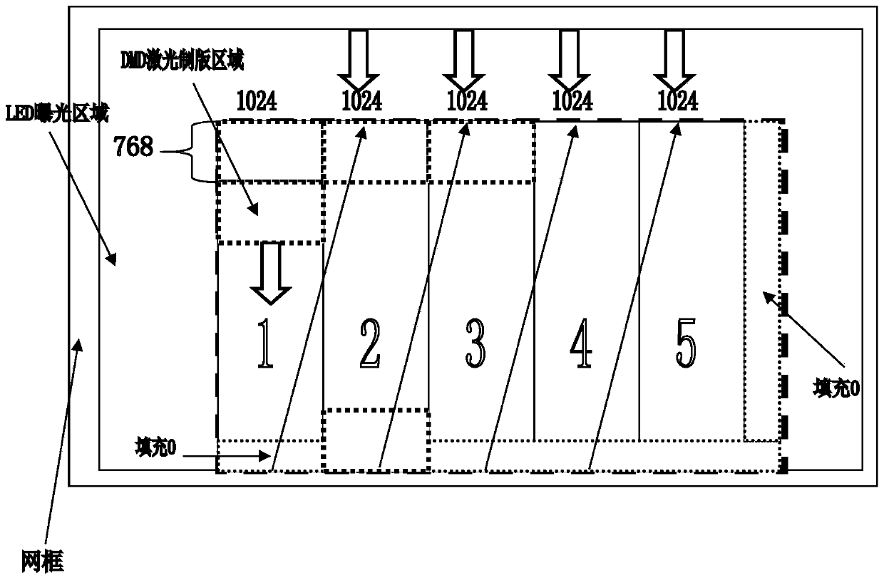
[0003] However, in practical applications, due to the influence of the proportion of the screen printing image in the screen printing plate making format, the exposure capacity of the direct writing screen plate making system using DMD is greatly limited. The specific reason is that the screen frame of the screen printing plate contains the screen printing image area and edge banding blank area, and the area of ​​edge banding blank area is generally large. DMD is the core component of the plate making machine and is a high-precision device. If the DMD direct writing exposure process is used for the entire screen plate, it will not only increase the digital micro The workload of the mirror device will reduce the overall plate making efficiency at the same time

Method used


Image

  • A direct-writing screen edge-banding plate-making machine and edge-banding method
  • A direct-writing screen edge-banding plate-making machine and edge-banding method
  • A direct-writing screen edge-banding plate-making machine and edge-banding method

Examples


Embodiment Construction

[0054] The following will clearly and completely describe the technical solutions in the embodiments of the present invention with reference to the accompanying drawings in the embodiments of the present invention. Obviously, the described embodiments are only some, not all, embodiments of the present invention. Based on the embodiments of the present invention, all other embodiments obtained by persons of ordinary skill in the art without making creative efforts belong to the protection scope of the present invention.

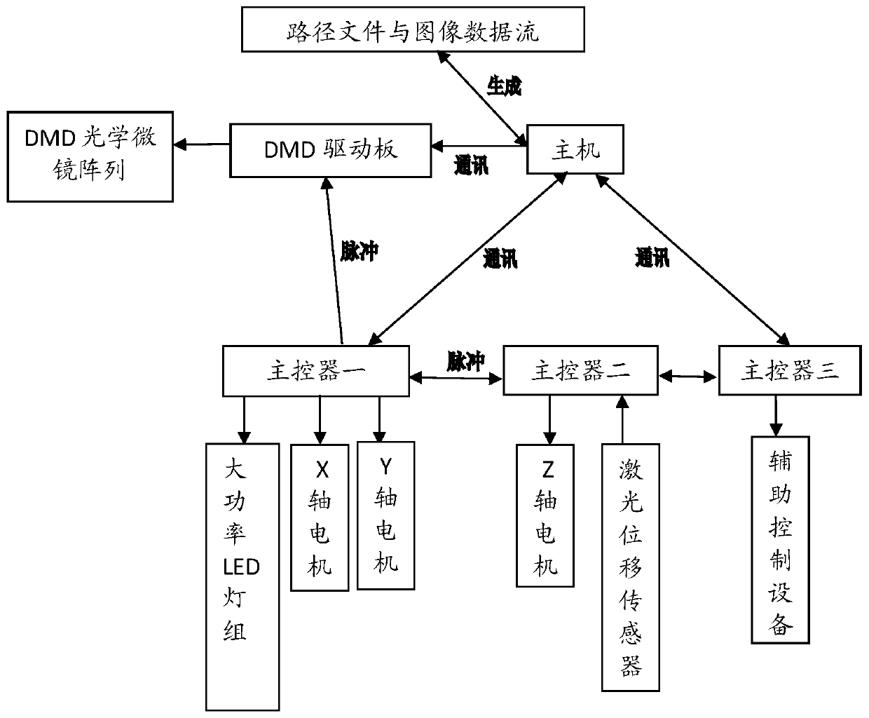
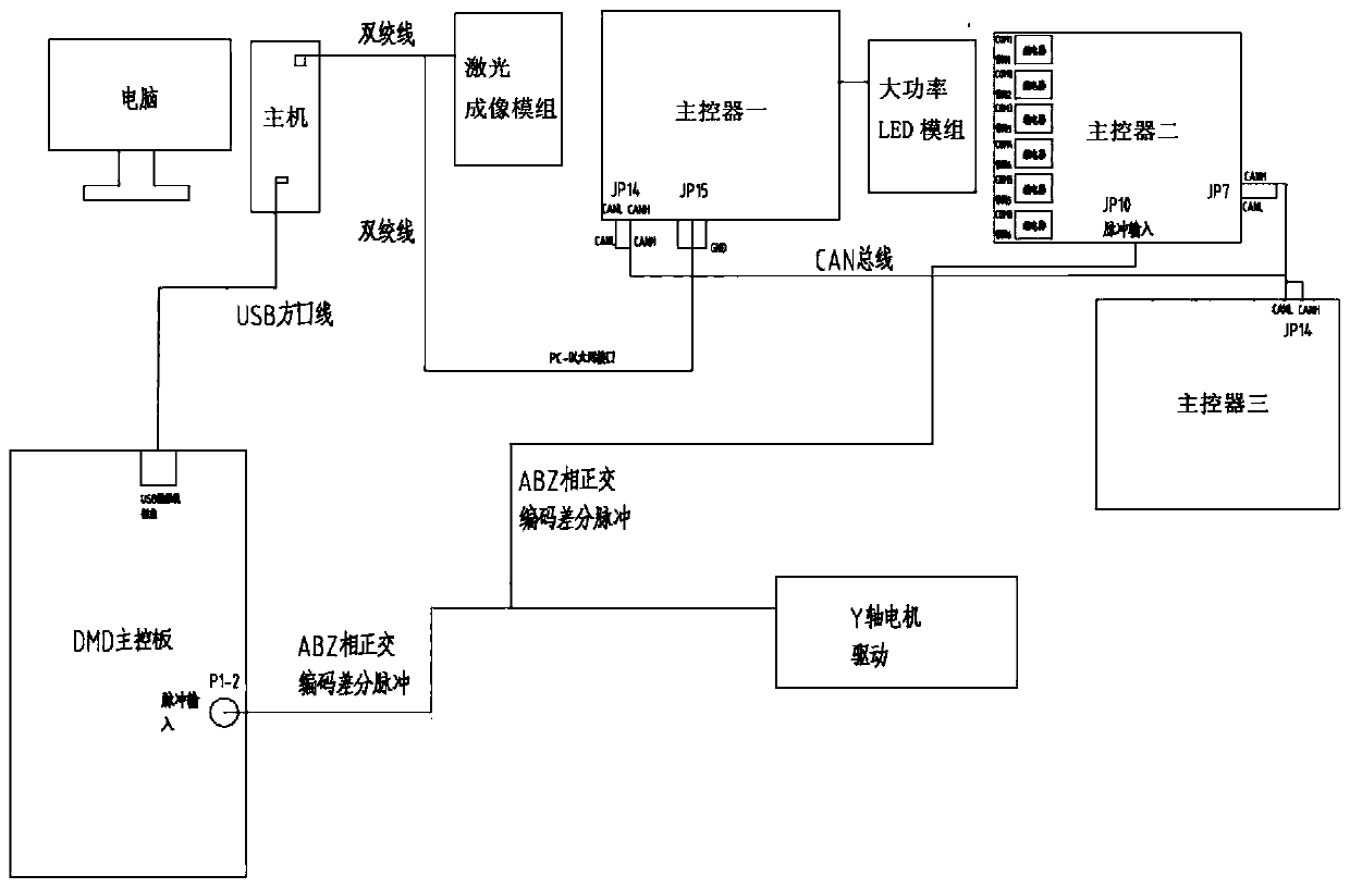
[0055] see figure 1 A schematic diagram of the working principle of the direct-writing screen edge banding plate making machine of the present invention is disclosed. The present invention adopts a plate-making method combining DMD laser direct plate-making and large-area exposure LED module, and the specific method is as follows:

[0056] S1, the host obtains the size of the screen plate and the position coordinates of the silk screen image on the screen pla...


PUM


Abstract

The invention discloses a direct writing-type screen edge sealing plate making machine and an edge sealing method. In a plate making way of combining DMD (digital micromirror device) laser direct plate making and a large-area exposure LED module, a path file is generated for each of a screen printing image area needing plate making and an edge sealing blank area on a screen plate, rapid exposure edge sealing is achieved through the LED module according to an LED edge sealing path first and then precise plate making is completed through a laser imaging system according to a DMD laser plate making path; in the process, an image expanding processing method is adopted for expanding the screen printing image area, so that the problem that the precision of a plate making part of a screen printing image is reduced due to coverage of an edge area of the screen printing image through LED light radiation is avoided. The plate making time is shortened, the plate making effect of the screen printing image is not affected, and the load of the laser imaging system is reduced; meanwhile, the service life of a DMD optical micromirror array is prolonged; the direct writing-type screen edge sealingplate making machine is simple in structure and easy to control, and effectively improves the plate making efficiency.

Description

technical field [0001] The invention relates to the technical field of screen printing plate making, and more specifically relates to a direct-writing screen edge banding plate making machine and an edge banding method. Background technique [0002] With the rapid development of digital technology, especially the development of semiconductor laser technology in recent years, and the direct plate-making technology of tablet computer has been widely used, the traditional method of screen printing plate-making is falling behind. One of the direct plate-making methods is to use a digital micromirror device (DMD) for exposure processing to realize direct plate-making, which can save time and reduce production costs. [0003] However, in practical applications, due to the influence of the proportion of the screen printing image in the screen printing plate making format, the exposure capacity of the direct writing screen plate making system using DMD is greatly limited. The specif...

Claims


Application Information

Patent Timeline
Patent Type & Authority Patents(China)
IPC IPC(8): G03F7/20
CPCG03F7/2004G03F7/2053
Inventor 石俊民佟帅马成如
Owner 北京弘浩千瑞科技有限公司
Learn More