Method and device used for automatic speed regulation of vehicle engine

An automatic speed regulation and engine technology, applied in engine control, machine/engine, governor, etc., can solve problems such as generator failure, installation and debugging difficulties, drift, etc., to save manual operation, simple installation, The effect of reducing mechanical wear

Active Publication Date: 2018-10-09
BEIJING PULIMEN ELECTRO MECHANICAL HIGH TECHN CO
View PDF6 Cites 1 Cited by
  • Summary
  • Abstract
  • Description
  • Claims
  • Application Information

AI Technical Summary

Problems solved by technology

The disadvantage of this speed regulation method is that as the vehicle's service time increases, the fixed position of the accelerator will drift corresponding to the engine speed. If the engine speed drifts below the normal operating speed of the generator, the generator will not work; and this The speed regulation method is only suitable for the case where the power of the on-board generator is fixed. Since the power of the on-board generator changes with the speed, when the load power of the on-board generator increases, the engine needs to provide a higher speed when the vehicle is parked. Not advisable; finally, the installation and debugging of stepped speed regulation is difficult, that is, the fixed position of the accelerator when parking must be adjusted repeatedly during installation, so that the generator can work normally when parking

Method used


Image

  • Method and device used for automatic speed regulation of vehicle engine
  • Method and device used for automatic speed regulation of vehicle engine
  • Method and device used for automatic speed regulation of vehicle engine

Examples


Embodiment Construction

[0029] In order to make the object, technical solution and advantages of the present invention clearer, the implementation manner of the present invention will be further described in detail below in conjunction with the accompanying drawings.

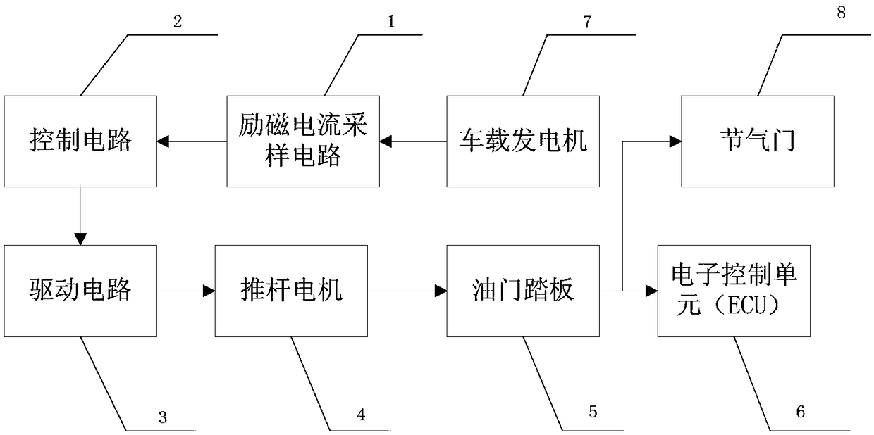
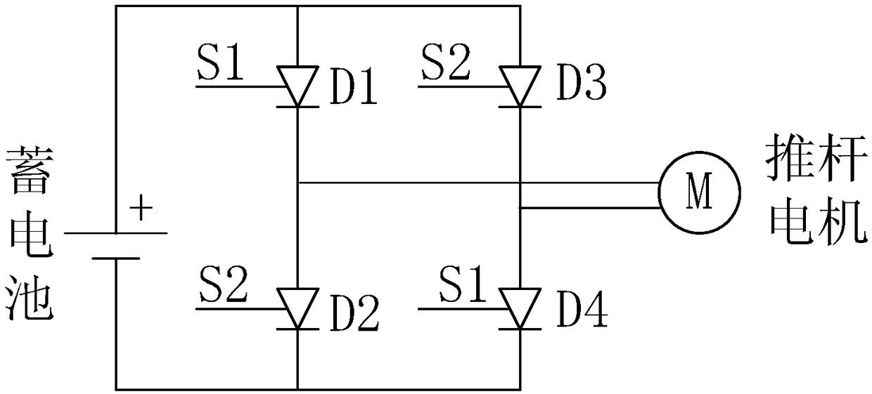
[0030] A vehicle engine automatic speed control device, its composition diagram is as follows figure 1 As shown, it includes an excitation current sampling circuit 1, a control circuit 2, a drive circuit 3, and a push rod motor 4. The push rod of push rod motor 4 is connected with vehicle accelerator pedal. In this embodiment, the push rod motor 4 is a DC motor. The drive circuit 3 includes a battery and an H-bridge.

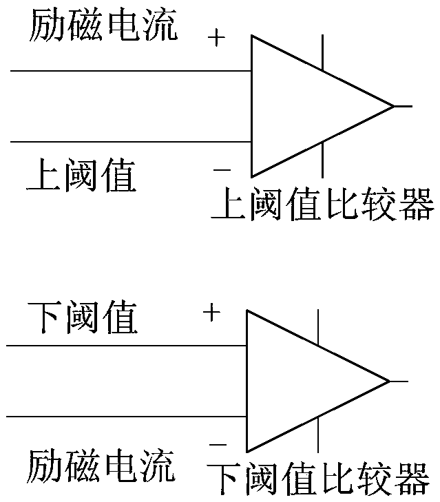
[0031] The excitation current sampling circuit 1 measures the excitation current value of the vehicle-mounted generator 7, then converts the excitation current value into a voltage signal and outputs it to the control circuit 2; the control circuit 2 judges according to the voltage signal, and outputs the drive signal ...


PUM


Abstract

The invention provides a method and device used for the automatic speed regulation of an engine when a special vehicle needs more power. The device comprises four parts, namely an exciting current sampling circuit, a control circuit, a driving circuit and a push rod motor. The method used for the automatic speed regulation of the vehicle parking engine is as follows: the exciting current samplingcircuit collects the exciting current value of a vehicle-mounted generator in real time; the control circuit judges whether the exciting current value is in a normal threshold range or not; and if exciting current exceeds the threshold and output power cannot meet load power, the control circuit outputs a positive voltage driving signal, a positive voltage driving axle arm of the driving circuit is electrified, the push rod motor clockwise rotates, the extension length of a push rod is longer, an accelerator pedal is pressed, the stroke is increased, and the rotating speed of the engine increases; and when the exciting current is lower than the threshold interval, the control circuit outputs a negative voltage driving signal, a negative voltage driving axle arm of the driving circuit is electrified, the push rod motor counterclockwise rotates, the extension length of the push rod is shorter, the stroke of the accelerator pedal is reduced, and the rotating speed of the engine decreases.

Description

technical field [0001] The invention relates to a method and a device for automatic speed regulation of a vehicle engine. Background technique [0002] When the vehicle is parked, the engine speed is too low, and the on-board generator cannot generate electricity normally. In order for the on-board generator to generate electricity normally when the vehicle is running at low speed or parked, it is necessary to increase the engine speed. If the engine speed is too high, the fuel consumption will increase, and if the engine speed is too low, the on-board generator will not work normally. Therefore, it is necessary to adjust the engine speed to the optimal speed according to the load of the on-board generator, so that the fuel consumption of the engine is small, and the on-board power generation The machine can also work normally. Although, when the vehicle is parked, the engine speed can be adjusted by manually stepping on the gas pedal, but when the vehicle is parked for to...

Claims


Application Information

Patent Timeline
Patent Type & Authority Applications(China)
IPC IPC(8): F02D11/10F02D31/00
CPCF02D11/10F02D31/001
Inventor 武紫玉王尚袁文成曹清张强呼锐锐杜鸿志
Owner BEIJING PULIMEN ELECTRO MECHANICAL HIGH TECHN CO
Why Eureka
Try Eureka