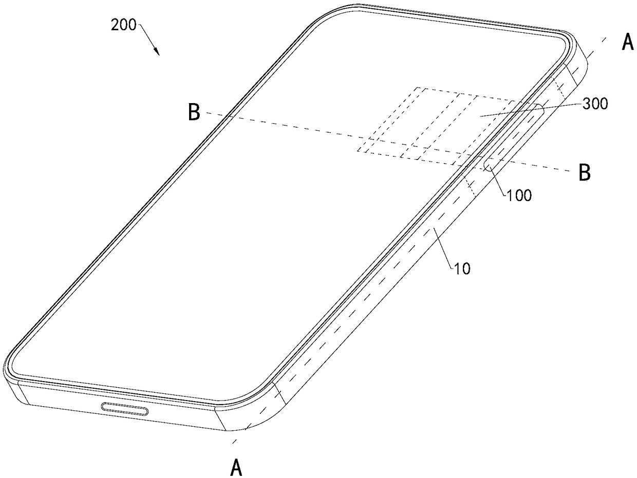
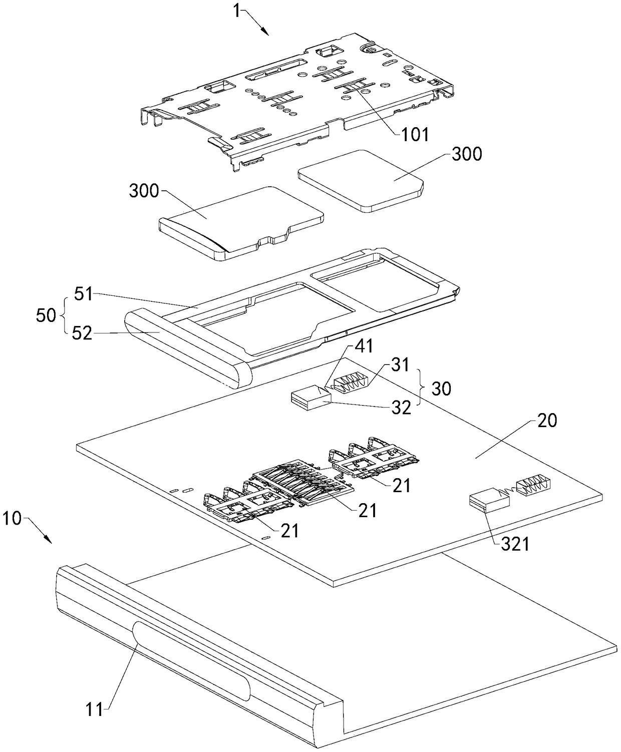
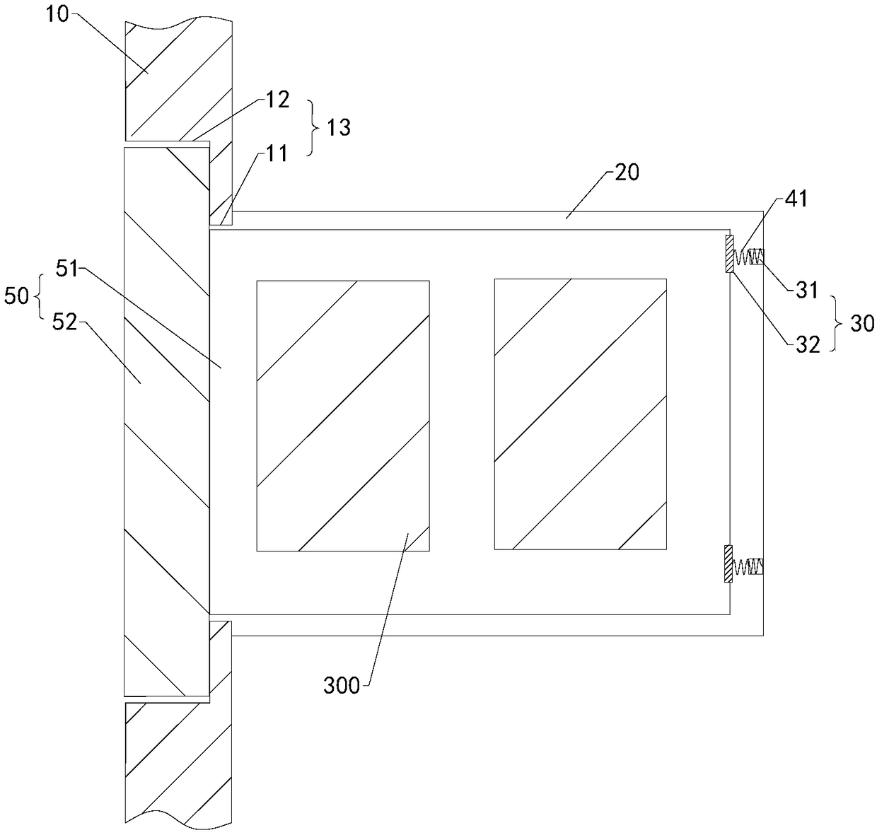
Card seat assembly, electronic device and control method thereof
A technology of electronic equipment and control method, which is applied to branch equipment, computer peripheral equipment connectors, circuits, etc., can solve the problems of inconvenient operation, inability to take out card trays and information cards, and unfavorable use by users, and achieves simple and convenient operation. The effect of taking the card
- Summary
- Abstract
- Description
- Claims
- Application Information
AI Technical Summary
Problems solved by technology
Method used
Image
Examples
Embodiment approach 1
[0041] Implementation mode one: if Image 6 As shown, the sidewall of the limiting groove 321 is provided with a first recessed area 3211 . The tray 51 is provided with a first protrusion 511 . When the tray 51 is inserted into the limiting slot 321 , the first protrusion 511 is accommodated in the first recessed area 3211 . In this embodiment, the first recessed area 3211 is in a strip shape. The shape of the outer surface of the first protrusion 511 is adapted to the shape of the surface of the first recessed area 3211 . When the user grasps the baffle plate 52 and applies a force to take it out, since the surface of the first recessed area 3211 is an arc surface, the first protrusion 511 of the tray 51 slides out of the first recessed area 3211 along the arc surface, thereby The card tray 50 is easily taken out from the inside of the casing 10 . In addition, because the groove wall of the limiting groove 321 is provided with the first recessed area 3211, the surface are...
Embodiment approach 2
[0042] Embodiment 2 is different from Embodiment 1 in that: if Figure 7 As shown, the sidewall of the limiting groove 321 is provided with a second protrusion 3212 . The card tray 50 is provided with a second recessed area 512 , and when the tray 51 is inserted into the limiting groove 321 , the second protrusion 3212 is accommodated in the second recessed area 512 . In this embodiment, the second protrusion 3212 is a strip-shaped structure. The shape of the outer surface of the second recessed area 512 is adapted to the shape of the surface of the second protrusion 3212 . When the user grasps the card tray 50 and applies a force to take it out, since the surface of the second protrusion 3212 is an arc surface, the second concave area 512 of the card tray 50 is separated from the second protrusion 3212 along the arc surface, Therefore, the card tray 50 can be easily taken out from the inside of the casing 10 . In addition, because the groove wall of the limiting groove 321...
Embodiment approach 3
[0043] Embodiment 3: In combination with Embodiment 1 and Embodiment 2, a first recessed area 3211 and a second protrusion 3212 are provided on the sidewall of the limiting groove 321 . The tray 51 is provided with a first protrusion 511 and a second recessed area 512 . When the tray 51 is inserted into the limiting groove 321, the first protrusion 511 is accommodated in the first recessed area 3211, and the second protrusion 3212 is engaged in the second recessed area 512 to further increase the position of the limiting groove 321. The static friction between the groove wall and the card holder 50 prevents the card holder 50 from coming out of the limiting groove 321 .
[0044] Such as Figure 8 As shown, the card seat assembly 100 includes a soft rubber part 60 , and the soft rubber part 60 is fixed on the groove wall of the limiting groove 321 . In this embodiment, the soft rubber part 60 is thermoplastic polyurethane elastomer rubber (Thermoplastic polyurethanes: TPU for...
PUM
 Abstract
Description
Claims
Application Information
 - R&D
- Intellectual Property
- Life Sciences
- Materials
- Tech Scout
- Unparalleled Data Quality
- Higher Quality Content
- 60% Fewer Hallucinations
Browse by: Latest US Patents, China's latest patents, Technical Efficacy Thesaurus, Application Domain, Technology Topic, Popular Technical Reports.
© 2025 PatSnap. All rights reserved.Legal|Privacy policy|Modern Slavery Act Transparency Statement|Sitemap|About US| Contact US: help@patsnap.com


