Dehumidifier

A dehumidifier and fan technology, which is applied in the field of air conditioning, can solve the problems of low dehumidification efficiency of dehumidifiers, and achieve the effects of ensuring efficient operation, reducing static pressure loss, and reducing air intake speed

Inactive Publication Date: 2018-10-02
GD MIDEA AIR-CONDITIONING EQUIP CO LTD +1
View PDF6 Cites 1 Cited by
  • Summary
  • Abstract
  • Description
  • Claims
  • Application Information

AI Technical Summary

Problems solved by technology

[0005] The main purpose of the present invention is to provide a dehumidifier aimed at solving the problem of low dehumidification efficiency of existing dehumidifiers

Method used


Image

  • Dehumidifier
  • Dehumidifier
  • Dehumidifier

Examples


Embodiment Construction

[0026] The following will clearly and completely describe the technical solutions in the embodiments of the present invention with reference to the accompanying drawings in the embodiments of the present invention. Obviously, the described embodiments are only part of the embodiments of the present invention, not all of them. Based on the embodiments of the present invention, all other embodiments obtained by persons of ordinary skill in the art without creative efforts fall within the protection scope of the present invention.

[0027] It should be noted that all directional indications (such as up, down, left, right, front, back...) in the embodiments of the present invention are only used to explain the relationship between the components in a certain posture (as shown in the accompanying drawings). Relative positional relationship, movement conditions, etc., if the specific posture changes, the directional indication will also change accordingly.

[0028] In addition, in t...


PUM


Abstract

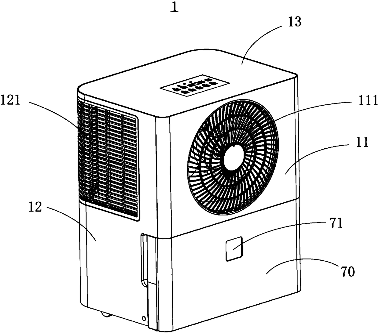
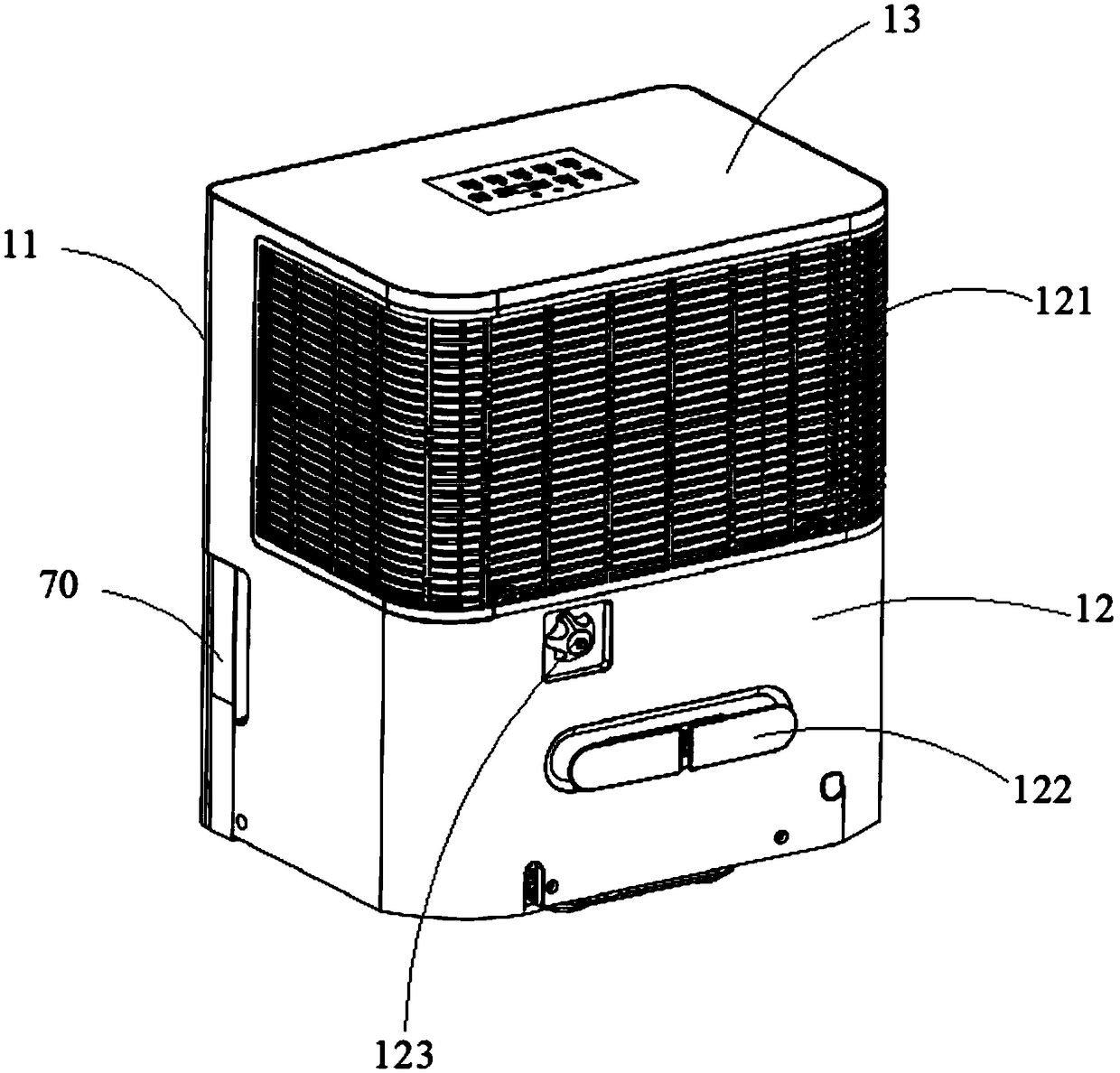
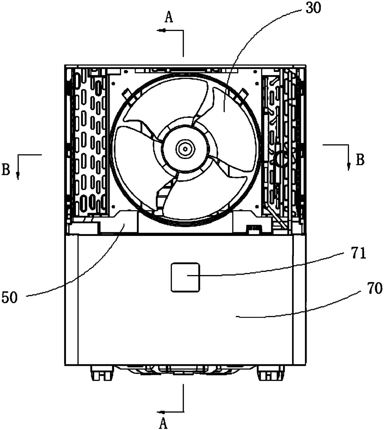
The invention discloses a dehumidifier. The dehumidifier comprises a shell, and further comprises a U-type heat exchanger, a fan, a volute, a middle partition plate, a compressor and a water tank which are arranged inside the shell; the middle partition plate is arranged between the U-type heat exchanger and the compressor; the fan is arranged inside the volute; the water tank is arranged below the volute; the shell is provided with an air inlet and an outlet; the U-type heat exchanger corresponds to the air inlet; the fan is arranged on the U-type inner side of the U-type heat exchanger; theair outlet direction of the fan faces the air outlet; and air is guided by the fan to enter via the U-type heat exchanger and then is blown out via the air outlet. The U-type heat exchanger of the dehumidifier is provided with three air inlet faces, so that a three-face air inlet channel is formed in the whole dehumidifier, compared with a single-face air inlet mode, the air processing area is increased, the air dehumidification efficiency is improved, noise generated during working of the dehumidifier is reduced, static pressure loss is reduced, and efficient operation of the fan can be ensured.

Description

technical field [0001] The invention relates to the technical field of air conditioning, in particular to a dehumidifier. Background technique [0002] Dehumidifiers can reduce the humidity in the ambient air. Commonly used dehumidifiers include evaporators, condensers, fans, etc. The air is powered by fans, and the evaporator first absorbs the heat of the air to condense the water vapor in the air to achieve the purpose of dehumidification. Then the condenser absorbs the heat of the refrigerant in the condenser to heat up, making the air reach the normal indoor temperature and forming a dry wind, thereby reducing the humidity in the air and keeping the temperature of the air basically stable when it passes through the dehumidification port. [0003] Existing dehumidifiers generally adopt a single-side air intake mode, and a centrifugal fan is used as a power to drive air circulation. The reason for using a centrifugal fan is that the dehumidifier needs many rows of evapora...

Claims


Application Information

Patent Timeline
Patent Type & Authority Applications(China)
IPC IPC(8): F24F1/02F24F3/14
CPCF24F3/14F24F2003/1446
Inventor 李伟明
Owner GD MIDEA AIR-CONDITIONING EQUIP CO LTD
Why Eureka
Try Eureka