Rotor structure of a drive motor

A technology of rotor structure and driving motor, applied in the direction of magnetic circuit shape/pattern/structure, electromechanical device, electrical components, etc., can solve the problems of increasing direct-axis reactance, affecting motor performance, lack of increase, etc., to improve the salient pole rate , Improve magnet utilization, efficiency and performance improvement

Active Publication Date: 2020-06-23
深圳市泉胜新技术开发有限公司
View PDF5 Cites 0 Cited by
  • Summary
  • Abstract
  • Description
  • Claims
  • Application Information

AI Technical Summary

Problems solved by technology

However, increasing the direct-axis ribs will increase the leakage flux, increase the direct-axis reactance, and affect the performance of the motor.
In the prior art, there is a lack of a technical solution that can meet the rigidity and strength requirements during high-speed rotation and avoid the increase of magnetic flux leakage

Method used


Image

  • Rotor structure of a drive motor

Examples


Embodiment Construction

[0017] The present invention will be further described below in conjunction with the accompanying drawings and specific embodiments.

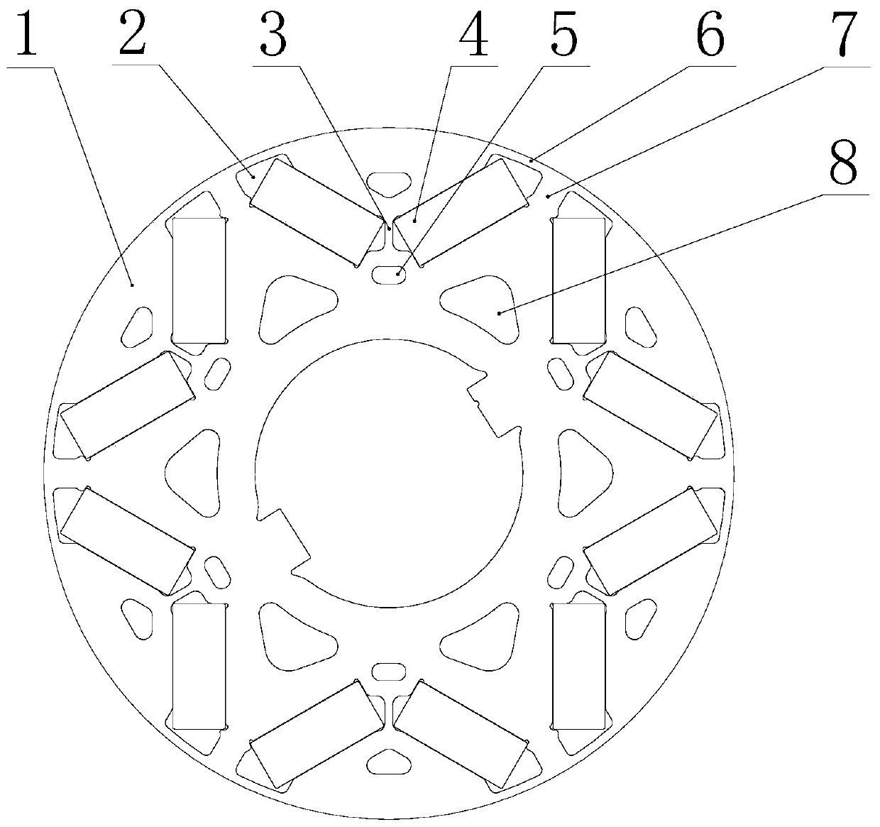
[0018] refer to figure 1 , the embodiment of the present invention provides a rotor structure for driving a motor, including a rotor punch 1, six V-shaped grooves 2 arranged in a circular array on the rotor punch 1, and a straight shaft is arranged in the middle of each V-shaped groove 2 Reinforcing rib 3, a rectangular magnetic steel 4 is inlaid on both sides of each V-shaped groove 2, an unloading hole 5 is opened under the straight axis reinforcing rib 3, and the outer ring of the rotor punch 1 is connected to each V-shaped groove 2. Magnetic isolation bridges 6 are provided at both ends of the groove 2, and an intersecting rib 7 is formed between two adjacent V-shaped grooves.

[0019] A first lightening hole 8 is opened between the two adjacent V-shaped groove groups; a second lightening hole is opened above the straight-axis reinforcing ...


PUM


Abstract

The invention discloses a rotor structure of a drive motor. The rotor structure comprises a rotor sheet and a plurality of V-shaped grooves, wherein the plurality of V-shaped grooves are circularly arrayed on the rotor sheet; a direct-axis reinforcing rib is arranged at a middle position of each of the V-shaped grooves; a rectangular magnetic steel is embedded into two edges of the each of the V-shaped grooves; and an unloading hole is formed below each of the direct-axis reinforcing ribs. According to the rotor structure, through the above structural design, the strength of the rotor structure is improved, an armature direct-axis magnetic circuit can be effectively hindered, the direct-axis inductance is reduced, the saliency ratio is improved, and the reluctance torque is improved; and furthermore, the leakage flux at the place is reduced, the utilization ratio of a magnet is improved, and the efficiency and performance of a motor applying the rotor are obviously improved.

Description

technical field [0001] The invention relates to the design field of permanent magnet motors, in particular to a rotor structure of a driving motor. Background technique [0002] Built-in permanent magnet motors are widely used in new energy electric vehicles because of their advantages such as high torque density, wide field weakening range and high operating efficiency. [0003] In the prior art, the rotor of the built-in permanent magnet motor generally protects the rotor from being deformed and damaged by its centrifugal force through a magnetic isolation bridge and cross-axis reinforcing ribs, and two pieces of magnetic steel are inserted into both sides of the V-shaped groove to fix them; some In order to further improve the structural strength of the rotor, the motor usually figure 1 A direct-axis stiffener is added to the middle of the V-shaped groove of the rotor punch in the middle, which can improve the rigidity and strength of the rotor, so as to ensure that the ...

Claims


Application Information

Patent Timeline
Patent Type & Authority Patents(China)
IPC IPC(8): H02K1/27H02K1/28
CPCH02K1/27H02K1/276H02K1/28
Inventor 沈哲林文泉易宇
Owner 深圳市泉胜新技术开发有限公司
Why Eureka
Try Eureka