Pasting apparatus for lead-acid battery plate grids

A lead-acid battery and paste coating technology, applied to lead-acid battery electrodes, devices for coating liquid on the surface, electrode collector coating, etc., can solve the problems of increasing processing technology, increasing manufacturing costs, and poor adaptability, etc. Achieve good structural stability, reduce production costs, and prevent grid deformation

Pending Publication Date: 2018-09-28
中国船舶重工集团衡远科技有限公司
View PDF7 Cites 0 Cited by
  • Summary
  • Abstract
  • Description
  • Claims
  • Application Information

AI Technical Summary

Problems solved by technology

[0002] The grid is one of the most important parts of the lead-acid battery. After the grid is produced, it needs to be filled with lead paste on the grid. The existing equipment for filling the lead paste is completed by a coating machine. The important equipment of the coating machine One is a plastering hopper, and the existing plastering hopper has the following defects: the existing plastering hopper cannot carry out lead plaster coating on a wider grid, and has poor adaptability, and if the wider grid For filling, it is necessary to change the feeding direction of the grid, so that the tabs of the grid will be covered with lead paste, which requires additional processing technology to clean the tabs, thereby increasing the manufacturing cost; and some existing coatings The stability of the plaster bucket is poor, and more importantly, the existing paste buckets tend to cause poor uniformity of the lead paste thickness of the grid during the paste coating process, and it is easy to cause deformation of the grid, which seriously affects the quality of the product

Method used


Image

  • Pasting apparatus for lead-acid battery plate grids
  • Pasting apparatus for lead-acid battery plate grids
  • Pasting apparatus for lead-acid battery plate grids

Examples


Embodiment Construction

[0037] Below in conjunction with accompanying drawing, the present invention is described in further detail, as shown in the figure:

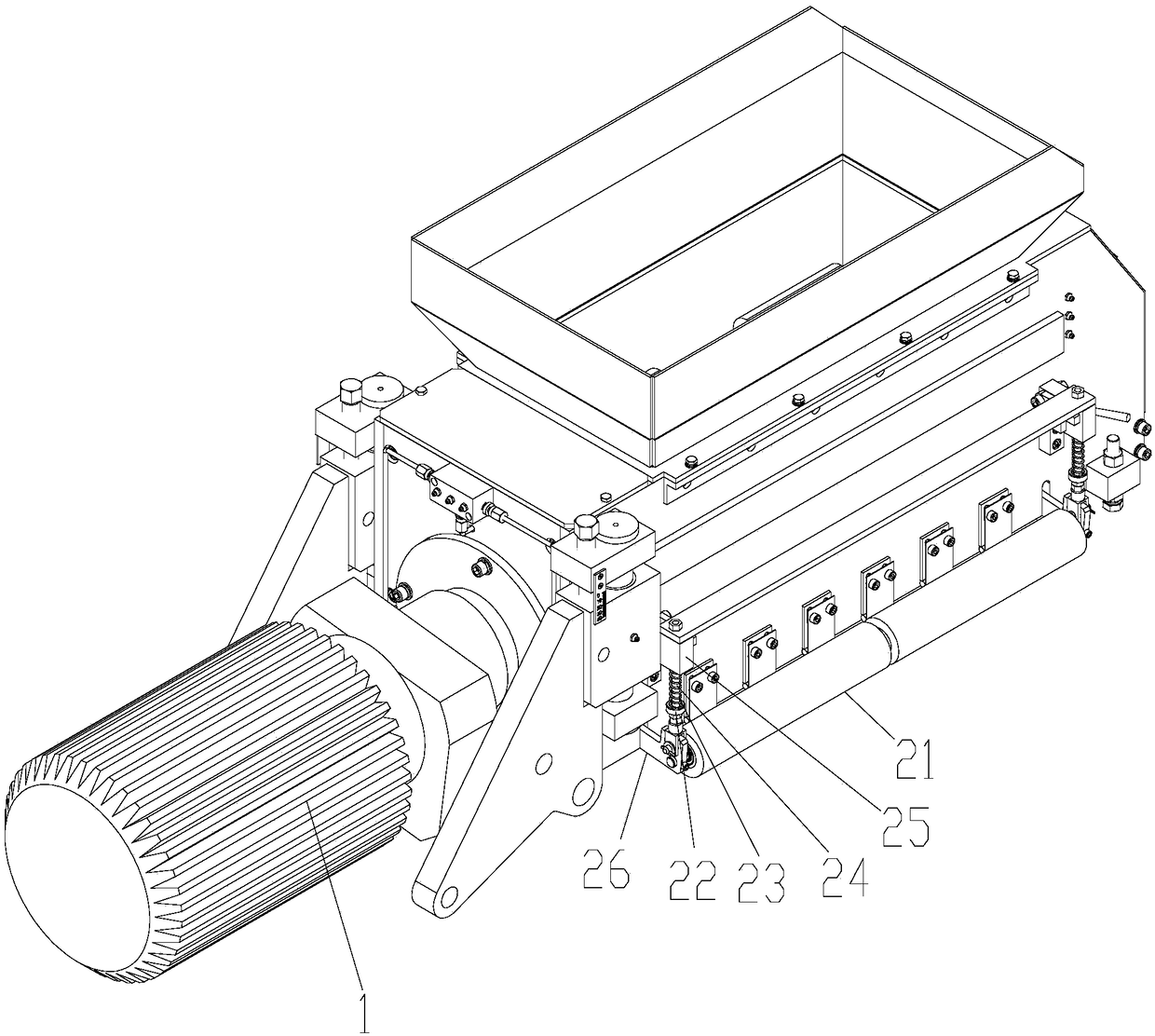
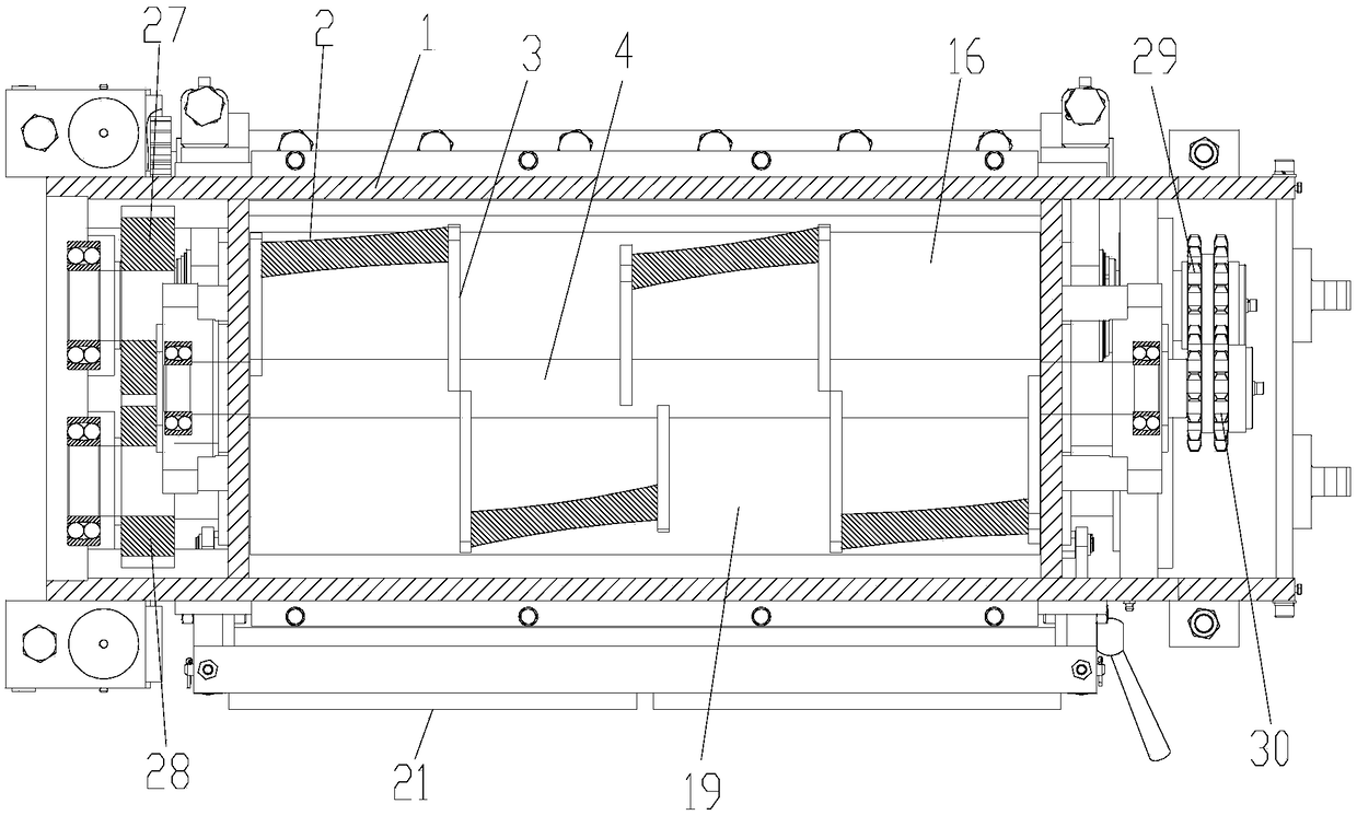
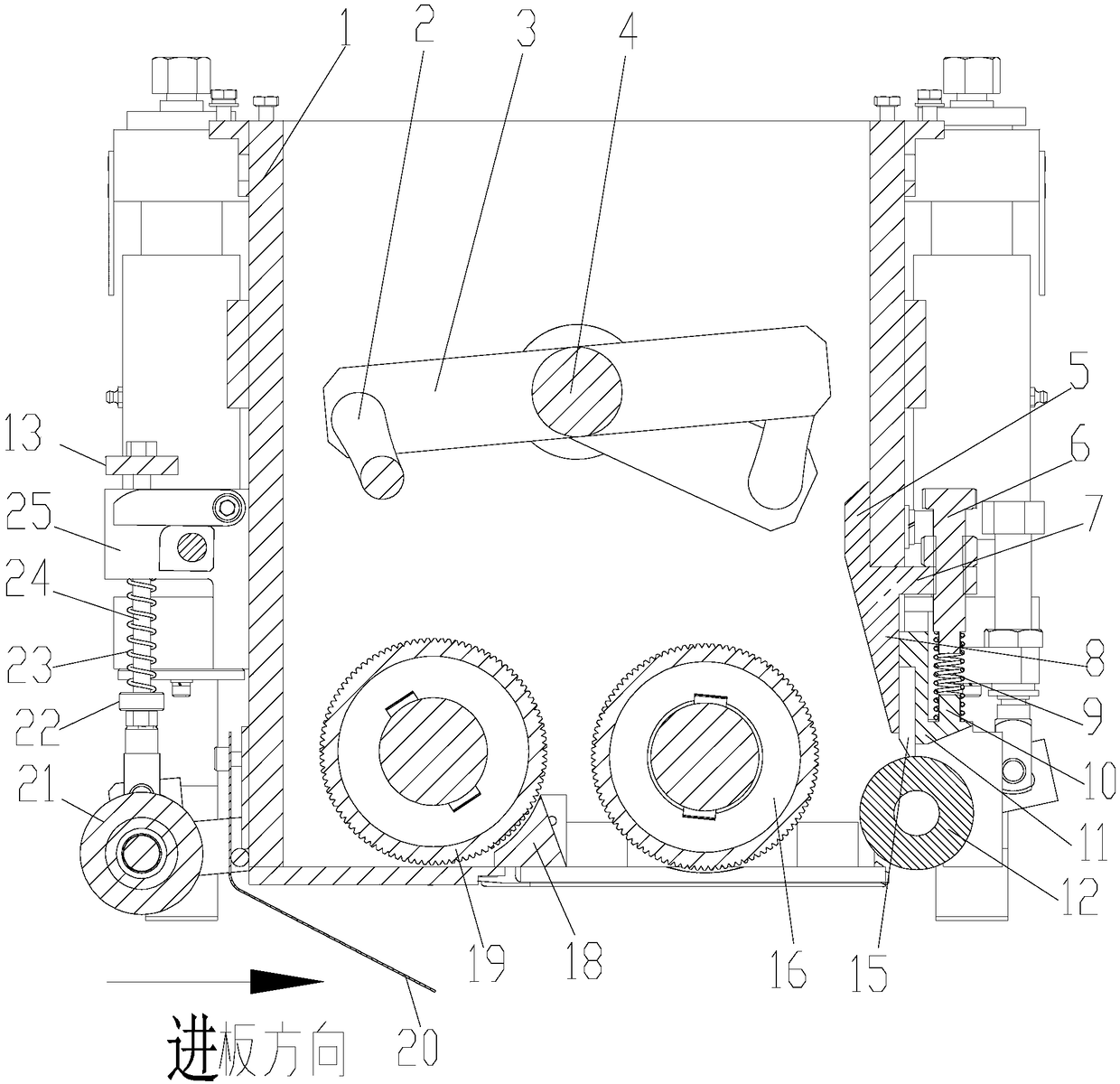
[0038] A kind of pasting device for lead-acid storage battery grid provided by the present invention comprises a pasting hopper 1, and a pasting roller 19, a pasting roller 16 and an agitator are arranged in the pasting hopper;

[0039] The paste extrusion roller 19 and the paste application roller 16 are rotatably arranged at the inner bottom of the paste application hopper 1, and the rotation directions of the paste extrusion roller 19 and the paste application roller 16 are opposite, and the paste extrusion roller 19 and the paste application roller 16 The axes are parallel and the paste extrusion roller 19 is arranged between the feeding plate end of the paste hopper 1 and the paste application roller 16, and the agitator is positioned above the paste extrusion roller 19 and the paste application roller 16;

[0040] The plate outlet end ins...


PUM


Abstract

The invention provides a pasting apparatus for lead-acid battery plate grids, comprising a pasting bucket; an extrusion roller, a pasting roller and a stirrer are disposed in the pasting bucket; the extrusion roller and the pasting roller are rotationally arranged at the inner bottom of the pasting bucket and rotate oppositely; axes of the extrusion roller and the pasting roller are parallel, theextrusion roller is arranged between the feed end of the pasting bucket and the pasting roller, and the stirrer is positioned above the extrusion roller and the pasting roller; the inner discharge endof the bottom of the pasting bucket is rotationally provided with a reverse roller; the rotational direction of the reverse roller is opposite to the plate grid discharging direction of a plate grid,and axes of the reverse roller and the pasting roller are parallel; during pasting, the stirrer performs stirring such that lead paste gains good uniformity; the extrusion roller and the pasting roller co-act, lead paste is never gathered; after the pasting roller performs lead pasting, extrusion pasting is further performed via the reverse roller; therefore, uniformity of the lead paste on the plate grid can be effectively ensured during pasting, and pasting quality is effectively ensured for the plate grid. The above structure causes no influence to lugs of the plate grid.

Description

technical field [0001] The invention relates to a lead-acid battery part processing equipment, in particular to a lead-acid battery grid pasting device. Background technique [0002] The grid is one of the most important parts of the lead-acid battery. After the grid is produced, it needs to be filled with lead paste on the grid. The existing equipment for filling the lead paste is completed by a coating machine. The important equipment of the coating machine One is a plastering hopper, and the existing plastering hopper has the following defects: the existing plastering hopper cannot carry out lead plaster coating on a wider grid, and its adaptability is poor. For filling, it is necessary to change the feeding direction of the grid, so that the tabs of the grid will be covered with lead paste, which requires additional processing technology to clean the tabs, thereby increasing the manufacturing cost; and some existing coatings The plaster hopper has poor stability, and mo...

Claims


Application Information

Patent Timeline
Patent Type & Authority Applications(China)
IPC IPC(8): H01M4/04H01M4/20B05C1/08B05C11/02
CPCH01M4/0404H01M4/20B05C1/0813B05C1/0865B05C11/023Y02E60/10
Inventor 熊金磊冯海冶鹏亮吴克海李兴
Owner 中国船舶重工集团衡远科技有限公司
Why Eureka
Try Eureka