Single-cavity unsymmetrical sliding-vane-type vacuum pump

An asymmetrical, sliding-vane technology used in rotary piston pumps, pumps, rotary piston/swing piston pump components, etc., to solve problems such as exhaust leakage, short seal contact lines, and connectivity, and to improve Internal leakage and good sealing effect

Active Publication Date: 2018-09-28
CHINA UNIV OF PETROLEUM (EAST CHINA)
View PDF8 Cites 0 Cited by
  • Summary
  • Abstract
  • Description
  • Claims
  • Application Information

AI Technical Summary

Problems solved by technology

[0004] In order to solve the problem that the internal volume ratio of the sliding vane vacuum pump caused by the existing circular cylinder profile is small, the sealing contact line between the rotor and the inner wall of the cylinder is short, and it is easy to cause the connection between the high-pressure chamber and the low-pressure chamber, resulting in exhaust leakage. , the present invention proposes a single-chamber asymmetrical vane vacuum pump. The cylinder profile on the cylinder is an asymmetric closed curve with continuous second-order derivatives. It is continuous and smooth without abrupt changes and without a center passing through the center of rotation. The line makes the cylinder profile symmetrical about its axis, and the gap between the cylinder profile and the outer contour line of the rotor gradually increases from C to A (including C and A points), and the pole diameter of the cylinder profile is determined by R 3 increase to R 3 +0.04, the polar diameter of the cylinder profile increases rapidly from point A to point B, and reaches the maximum at point B, the curve shape rises steeply from point A to point B, and starts from the polar diameter of the cylinder profile from point B to point C Gradually decreases, the curve gradually becomes flat

Method used


Image

  • Single-cavity unsymmetrical sliding-vane-type vacuum pump
  • Single-cavity unsymmetrical sliding-vane-type vacuum pump
  • Single-cavity unsymmetrical sliding-vane-type vacuum pump

Examples


Embodiment Construction

[0028] The present invention will be further described below in conjunction with the accompanying drawings and embodiments.

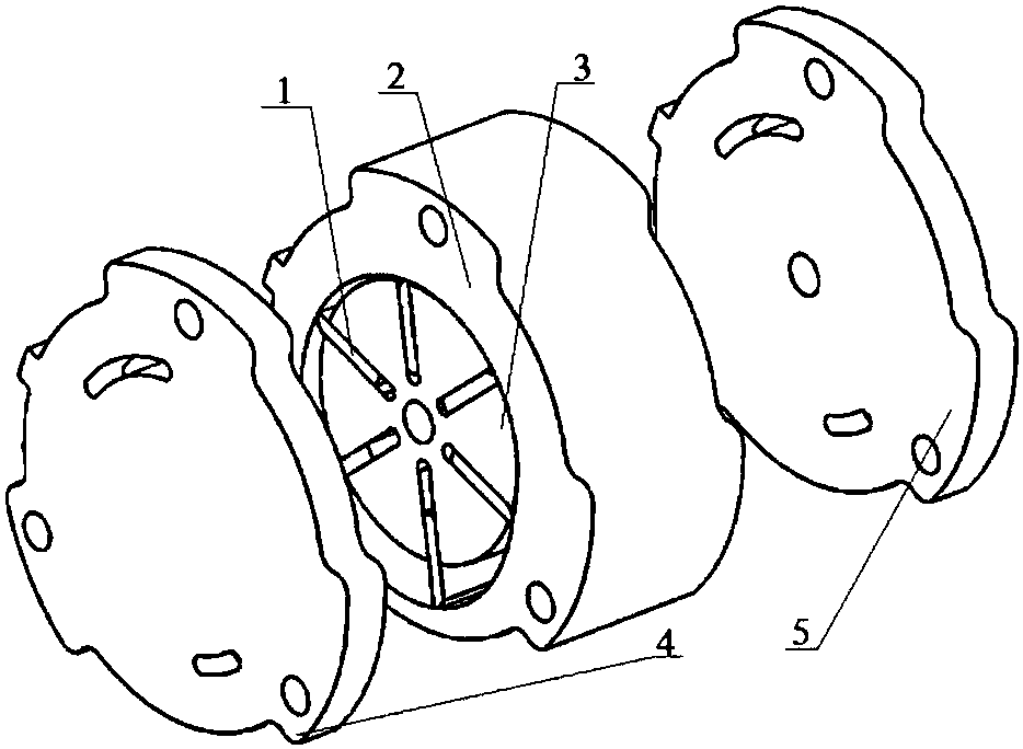
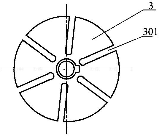
[0029] Such as figure 1 As shown, it is a schematic diagram of the assembly relationship of a single-cavity asymmetric sliding vane vacuum pump, and the components of the sliding vane (1), cylinder (2), rotor (3), upper end cover (4) and lower end cover (5) are assembled to obtain Schematic diagram of the assembly relationship.

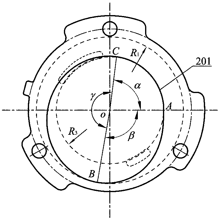
[0030] Such as figure 2 As shown, it is the main figure of the cylinder profile, the cylinder profile (201) on the cylinder (2) is an asymmetrical closed curve with continuous second-order derivatives, that is, the points of the cylinder profile (201) are continuous and smooth. There is a sudden change point, and there is no center line passing through its center of rotation O so that the cylinder profile (201) is symmetrical about its axis; the cylinder profile (201) is the coordinate origin with its center of rotation O, a...


PUM


Abstract

The invention discloses a single-cavity unsymmetrical sliding-vane-type vacuum pump, and relates to the field of fluid machinery. The single-cavity unsymmetrical sliding-vane-type vacuum pump is mainly composed of a sliding vane (1), an air cylinder (2), a rotor (3), an upper end cover (4) and a lower end cover (5); an air cylinder profile (201) is a second derivative continuous unsymmetrical closed curve and is continuous and smooth, no catastrophe point exists, moreover, no center line passing through the rotation center exists, and the air cylinder profile (201) is symmetrical about the axis of the air cylinder profile (201); and in the working process, through a work cavity of which the volume can be periodically changed, air suction, compression and air exhaust of the sliding-vane-type vacuum pump are achieved. According to the single-cavity unsymmetrical sliding-vane-type vacuum pump, the inner volume ratio of the sliding-vane-type vacuum pump can be effectively increased, the sealing gag between the air cylinder profile (201) and the outer contour line of the rotor (3) is small, the top end of the sliding vane (1) is always attached to the inner wall face of the air cylinder(2) in the air exhaust process, and air exhaust and sealing of the sliding-vane-type vacuum pump are facilitated; and meanwhile, stress of the sliding vane (1) is advantageously perfected, and friction losses are reduced.

Description

technical field [0001] The invention belongs to the field of fluid machinery, in particular to a single-chamber asymmetrical vane vacuum pump. Background technique [0002] The sliding vane vacuum pump is a rotary positive displacement vacuum pump, which realizes the suction, pressurization and exhaust of gas through the periodically changing crescent-shaped chamber formed between the outer cylindrical surface of the rotor and the inner wall of the cylinder; Small size, few parts, low noise and stable operation are widely used in pre-vacuum pump air extraction equipment and automobile brake booster system. The cylinder profile of a common single-chamber sliding vane vacuum pump is usually circular. This type of cylinder profile will cause the internal volume ratio of the sliding vane vacuum pump to be small, and the sealing contact line between the rotor and the inner wall of the cylinder is short, which is likely to cause high-pressure cavity The communication with the low...

Claims


Application Information

Patent Timeline
Patent Type & Authority Applications(China)
IPC IPC(8): F04C18/344F04C25/02F04C29/00
CPCF04C18/344F04C25/02F04C29/00F04C2250/301
Inventor 王君陈志凯崔淑洁魏蜀红杨舒然冯浩志李薪池
Owner CHINA UNIV OF PETROLEUM (EAST CHINA)
Why Eureka
Try Eureka