
Method of building oil dredging well channel

A channel and oil well technology, used in earth-moving drilling, wellbore/well components, cleaning appliances, etc., can solve the problems of crude oil condensation, difficulty in running oil extraction, blockage, etc., to achieve large cost advantages and effectively establish fishing Oil channel, release the effect of unclean pressure relief

Active Publication Date: 2018-09-28
PETROCHINA CO LTD
View PDF8 Cites 2 Cited by
  • Summary
  • Abstract
  • Description
  • Claims
  • Application Information

AI Technical Summary

Problems solved by technology

[0002] In oil wells with high crude oil viscosity, for example, when the viscosity of crude oil is about 10,000 centipoise, the crude oil will condense when the temperature drops. Crude oil, so there will be a problem that it is difficult to extract oil and pump it down
[0003] At present, the main method to solve the problem that oil wells cannot be fished due to viscous crude oil is downhole minor repair operation. Specifically, the operation machine is used to run the tubing into the well and perform circular hot washing to thoroughly clean the viscous oil on the casing wall of the wellbore. crude oil and scaling, but the above-mentioned operation method has the following problems: the first operation requires sufficient area around the well site to place derricks, place oil pipes, and park hot-wash pump trucks and water tank trucks. The well site cannot meet the operation and construction conditions; secondly, after the operation channel is established, it is necessary to move the operating machine and clean the oil pipes in the well site before the next oil fishing operation can be carried out. Condensation forms and blocks thick oil, which makes it difficult to lower the oil pump

Method used


Image

  • Method of building oil dredging well channel
  • Method of building oil dredging well channel
  • Method of building oil dredging well channel

Examples


Embodiment Construction

[0037] The details of the present invention can be understood more clearly with reference to the accompanying drawings and the description of specific embodiments of the present invention. However, the specific embodiments of the present invention described here are only for the purpose of explaining the present invention, and should not be construed as limiting the present invention in any way. Under the teaching of the present invention, the skilled person can conceive any possible modification based on the present invention, and these should be regarded as belonging to the scope of the present invention. It should be noted that when an element is referred to as being “disposed on” another element, it may be directly on the other element or there may also be an intervening element. When an element is referred to as being "connected to" another element, it can be directly connected to the other element or intervening elements may also be present. The terms "mounted", "connec...


PUM


Abstract

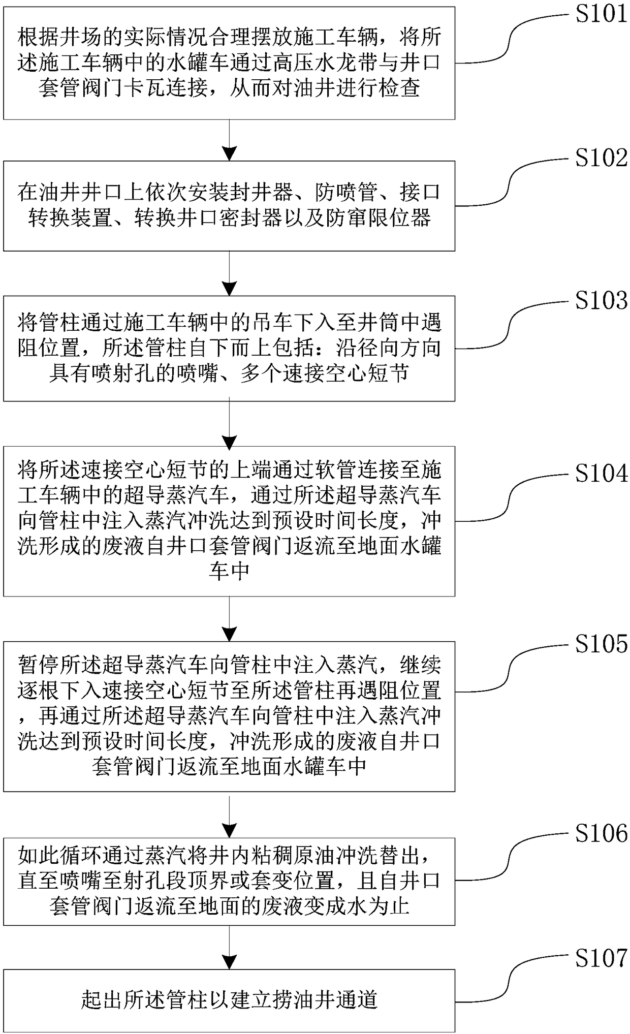
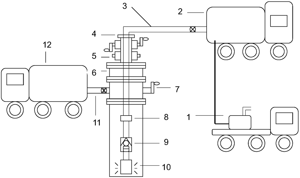
The invention discloses a method of building an oil dredging well channel, and relates to the field of oil and gas exploitation. The method comprises the following steps that construction vehicles arereasonably placed according to the practical situation of a well site, and a water-tank lorry, among the construction vehicles, is connected with a wellhead casing pipe valve by a high-pressure waterhose in a slipping mode, so that an oil well is detected; a well plugging device, a spray-proof pipe, a connecting-opening conversion device, a wellhead conversion sealer and an anti-channeling limiter are mounted on a wellhead of the oil well in sequence; and a tubular column is lowered into a tight-pull position in a well shaft by a crane among the construction vehicles, wherein the tubular column comprises a nozzle with spray-holes in the radial direction, a plurality of quick connected hollow nipples and the like from bottom to top. Thick or congealed crude oil on the wall surface of a casing pipe can be treated in a place with a relatively small area in the well site, and then the oil dredging channel is quickly built; and compared with minor repair operation, the operation cost is effectively reduced.

Description

technical field [0001] The invention relates to the field of oil and gas exploitation, in particular to a method for establishing an oil well channel. Background technique [0002] In oil wells with high crude oil viscosity, for example, when the viscosity of crude oil is about 10,000 centipoise, the crude oil will condense when the temperature drops. crude oil, which will lead to the problem of difficulty in oil pumping and lowering. [0003] At present, the main method to solve the problem that oil wells cannot be fished due to viscous crude oil is downhole minor repair operation. Specifically, the operation machine is used to run the tubing into the well and perform circular hot washing to thoroughly clean the viscous oil on the casing wall of the wellbore. crude oil and scaling, but the above-mentioned operation method has the following problems: the first operation requires sufficient area around the well site to place derricks, place oil pipes, and park hot-wash pump ...

Claims


Application Information

Patent Timeline
Patent Type & Authority Applications(China)
IPC IPC(8): E21B37/00E21B43/24
CPCE21B37/00E21B43/24
Inventor 李作臣郭明刚王勇强张秋爽李晖李皓楠郭政曈
Owner PETROCHINA CO LTD
Learn More