
Pierced type material receiving device with machine tool material removal function

A splicing device and hollow-out technology, which is applied in the field of hollow-out machine tool material cleaning splicing device, can solve the problems of inability to discharge waste, scratches, and waste falling on the surface of the splicing mechanism, etc., to ensure smoothness, Accurately detect the effect of increasing kinetic energy

Pending Publication Date: 2018-09-28
CHONGQING HONGGANG CNC MACHINE TOOL
View PDF12 Cites 2 Cited by
  • Summary
  • Abstract
  • Description
  • Claims
  • Application Information

AI Technical Summary

Problems solved by technology

However, this material receiving mechanism has the following problems: for turning disc materials, it is mainly to turn the annular groove on the side wall, so that after turning, a lot of waste will accumulate in the annular groove and cannot be discharged
At the same time, even if the waste chips are discharged from the ring groove, it is easy to cause the waste chips to fall on the surface of the material receiving mechanism, and it is not easy to clean them in time, which will scratch or adhere to the surface of the disc material behind, affecting the circular ring. The quality of the tray material

Method used


Image

  • Pierced type material receiving device with machine tool material removal function
  • Pierced type material receiving device with machine tool material removal function
  • Pierced type material receiving device with machine tool material removal function

Examples


Embodiment Construction

[0022]The present invention will be described in further detail below by means of specific embodiments:

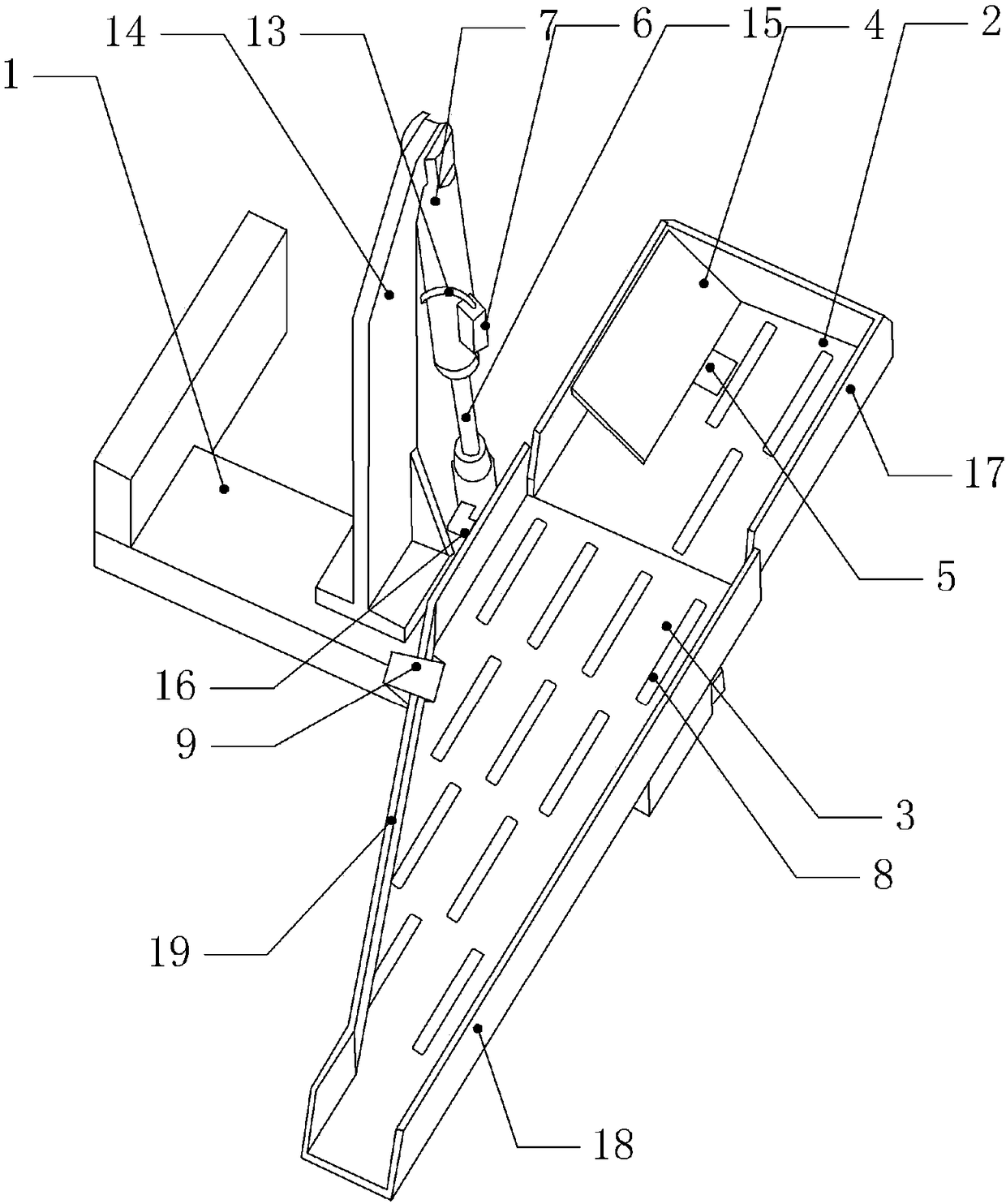
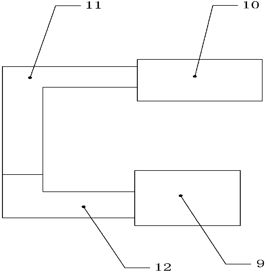
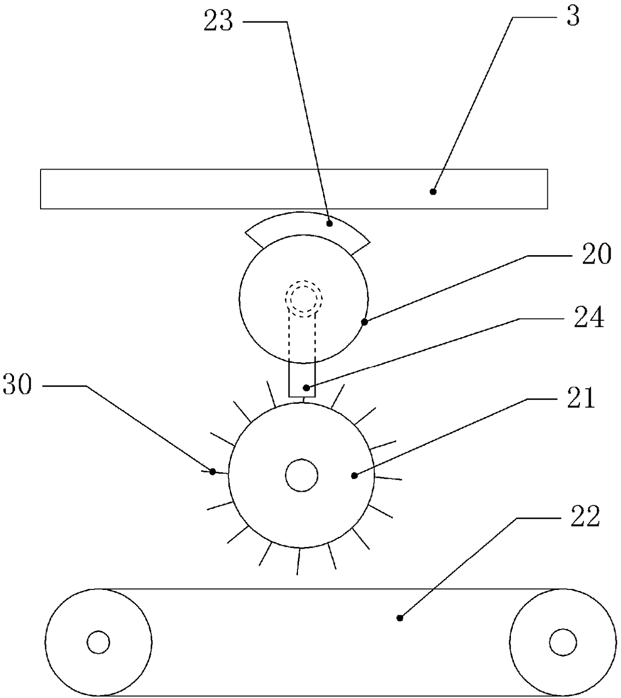
[0023] The reference signs in the drawings of the description include: fixed frame 1, rotary receiving tray 2, fixed receiving tray 3, guide plate 4, pressure sensor 5, first air pump 6, pushing cylinder 7, chip removal hole 8, second An air spray head 9, the second air pump 10, the second air pipe 11, the second flexible pipe 12, the first air pipe 13, the first support rod 14, the first piston rod 15, the second support rod 16, the first vertical plate 17, The second vertical plate 18, the third vertical plate 19, the first turntable 20, the second turntable 21, the transmission mechanism 22, the magnet 23, the second air spray head 24, the first rotating shaft 25, the fixed pipe 26, the third support rod 27 , ventilation cavity 28, first hose 29, bristles 30, first incomplete gear 31, second incomplete gear 32, bump 33, drive rod 34, second rotating shaft 35, first moto...


PUM


Abstract

The invention relates to the technical field of machine tools, and discloses a pierced type material receiving device with the machine tool material removal function. The pierced type material receiving device with the machine tool material removal function comprises a fixed rack, and further comprises a rotary material receiving disk and a fixed material receiving disk. The fixed material receiving disk is arranged in a downwards inclined manner and is connected to the fixed rack. The high end of the fixed material receiving disk is hinged to the rotary material receiving disk. A material outlet is formed in the low end of the fixed material receiving disk. The fixed rack is provided with a driving mechanism to drive the rotary material receiving disk to rotate. A guide plate is arrangedon one side of the rotary material receiving disk. The guide plate is arranged in a downwards inclined manner. A pressure sensor and a controller are arranged on the side, close to the guide plate, ofthe rotary material receiving disk. Multiple scrap discharge holes are formed in the rotary material receiving disk. Multiple scrap discharge holes are formed in the fixed material receiving disk. Afirst jet head and an air supply mechanism are installed on one side of the fixed material receiving disk. The pierced type material receiving device with the machine tool material removal function can discharge waste materials in circular grooves out in time.

Description

technical field [0001] The invention relates to the technical field of machine tools, in particular to a hollowed-out machine tool material cleaning device. Background technique [0002] Turning means that machine tool processing is a kind of mechanical processing. Machine tool processing mainly uses turning tools to turn rotating materials. Machine tools are mainly used to process shafts, discs, sleeves and other workpieces with rotating surfaces, and are the most widely used type of machine tool processing in machinery manufacturing and repair factories. Existing machine tools mainly include turning mechanism, material receiving mechanism and detection mechanism. Among them, the material receiving mechanism, as an intermediate link, plays a role of connecting the previous and the next, which is of great significance. At present, the existing material receiving mechanism mainly plays the role of transferring materials. The material receiving plate of the material receivin...

Claims


Application Information

Patent Timeline
Patent Type & Authority Applications(China)
IPC IPC(8): B23B13/00B23Q11/00
CPCB23Q7/00B23Q11/005
Inventor 汪传宏
Owner CHONGQING HONGGANG CNC MACHINE TOOL
Learn More