
Plastic particle metal separator

A metal separator and plastic particle technology, applied in the field of metal separators, can solve problems such as material waste, and achieve the effect of reducing material waste

Inactive Publication Date: 2018-09-28
JIANGSU FEILU HEAVY MACHINERY MFG CO LTD
View PDF2 Cites 0 Cited by
  • Summary
  • Abstract
  • Description
  • Claims
  • Application Information

AI Technical Summary

Problems solved by technology

[0003] Although the existing metal separator can meet the requirements of use to a certain extent, when metal is detected, the automatic removal device will remove all suspicious materials. Although the metal is effectively removed, a large number of metal-free materials are also removed. out, resulting in material waste

Method used


Image

  • Plastic particle metal separator

Examples


Embodiment Construction

[0016] The present invention will be further described below in conjunction with the accompanying drawings and specific embodiments, so that those skilled in the art can better understand the present invention and implement it, but the examples given are not intended to limit the present invention.

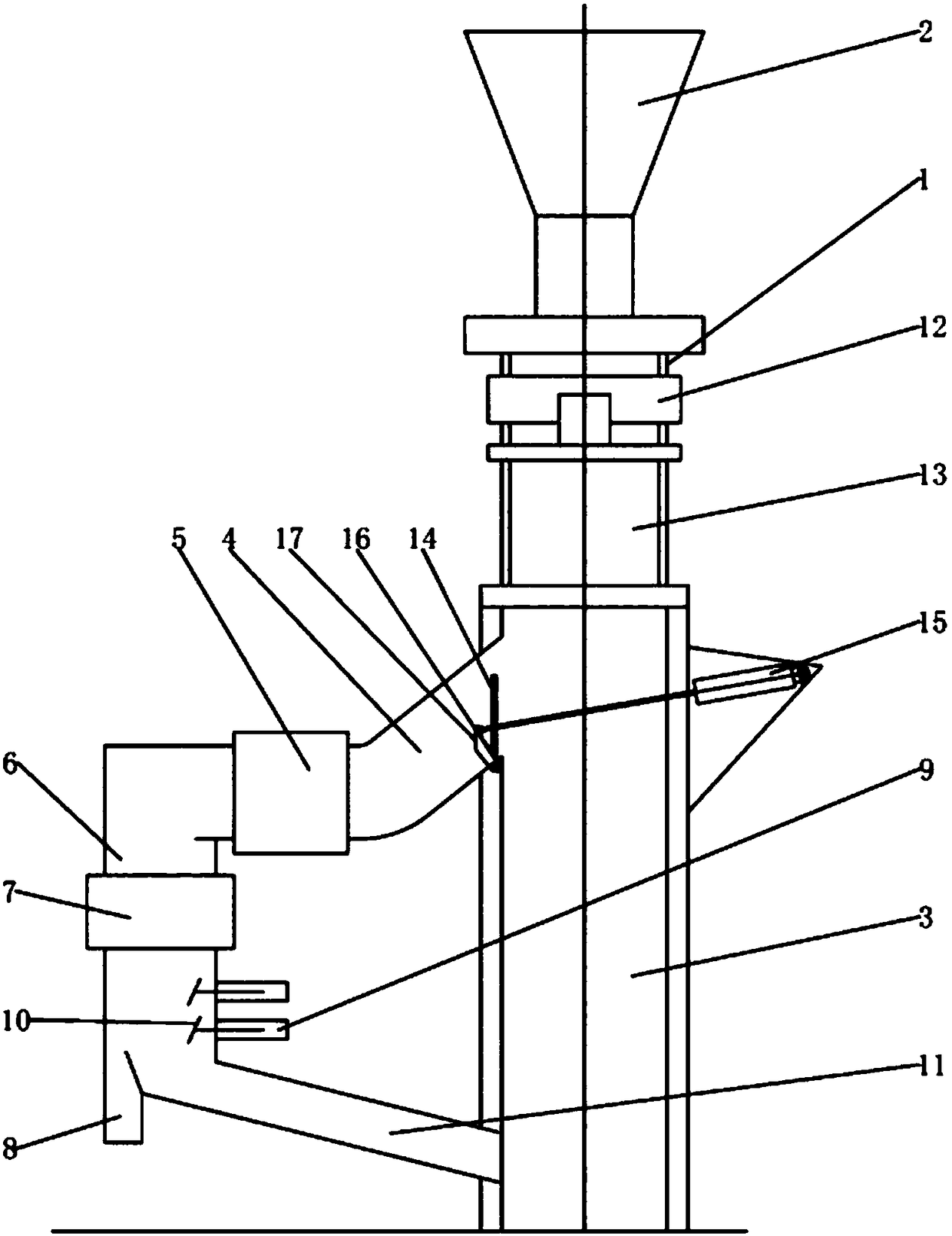
[0017] Such as figure 1 Shown is a schematic structural view of an embodiment of the metal separator for plastic particles of the present invention. The metal separator for plastic particles in this embodiment includes a metal detection channel 1, a feed hopper 2 is provided above the metal detection channel 1, a discharge channel 3 is provided below, and a rejecting channel 4 is provided on one side of the discharge channel 3, A metal detector 12 is provided in the metal detection channel 1 , and an automatic rejecting mechanism is provided between the discharge channel 3 and the rejecting channel 4 . A fine-picking mechanism is also arranged in the rejecting channel 4 .

[001...


PUM


Abstract

The invention discloses a plastic particle metal separator, which comprises a metal detection channel. A feed hopper is arranged above the metal detection channel, and a discharging channel is arranged below the metal detection channel. One side of the discharging channel is provided with a culling channel. A metal detector is arranged inside the metal detection channel. An automatic culling mechanism is arranged between the discharging channel and the culling channel. A fine culling mechanism is also arranged in the culling channel. The fine culling mechanism comprises a slow descending device which is arranged on the culling channel and decreases vertical velocity of the material to zero. A fine culling channel is arranged below the slow descending device. A second metal detector is arranged on the fine culling channel. A directional culling mechanism is arranged below the second metal detector. The culling channel is provided with a culling outlet positioned at one side of the directional culling mechanism. The directional culling mechanism comprises culling cylinders which are juxtaposed from top to bottom in the fine culling channel. The piston rod of each culling cylinder isprovided with a push plate used for pushing metal-containing plastic particles to the culling outlet.

Description

technical field [0001] The invention relates to a metal separator, in particular to a metal separator for plastic particles. Background technique [0002] Metal separators use the principle of electromagnetic induction to detect metals. All metals including ferrous and non-ferrous sensitivity. The entry of ferromagnetic metals into the detection area will affect the distribution of magnetic field lines in the detection area, thereby affecting the magnetic flux in a fixed range. Non-ferromagnetic metals entering the detection area will produce eddy current effects, which will also change the magnetic field distribution in the detection area. Usually, the metal separator is composed of two parts, namely the metal detector and the automatic rejection device, of which the detector is the core part. There are three sets of coils distributed inside the detector, that is, the central transmitting coil and two equivalent receiving coils. The oscillator connected to the middle tran...

Claims


Application Information

Patent Timeline
Patent Type & Authority Applications(China)
IPC IPC(8): B07C5/34B07C5/36
CPCB07C5/34B07C5/362B07C2501/0036
Inventor 张宗良
Owner JIANGSU FEILU HEAVY MACHINERY MFG CO LTD
Learn More