
An optical coherence tomography device based on a wave front dividing interferometer

An optical coherence tomography, imaging device technology, applied in the measurement of phase influence characteristics, etc., can solve the problems of affecting imaging sensitivity and large loss of signal light, and achieve the effect of eliminating adverse effects, reducing system adjustment requirements, and eliminating loss.

Active Publication Date: 2018-09-25
HUAIYIN INSTITUTE OF TECHNOLOGY
View PDF11 Cites 7 Cited by
  • Summary
  • Abstract
  • Description
  • Claims
  • Application Information

AI Technical Summary

Problems solved by technology

[0005] The technical problem to be solved by the present invention is to provide an optical coherence tomography device based on a split-wave front interferometer, which can solve the problem that the existing optical coherence tomography device has a large loss of signal light and affects imaging sensitivity

Method used


Image

  • An optical coherence tomography device based on a wave front dividing interferometer
  • An optical coherence tomography device based on a wave front dividing interferometer
  • An optical coherence tomography device based on a wave front dividing interferometer

Examples


Embodiment Construction

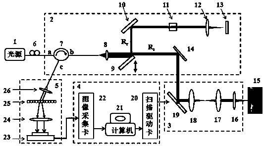
[0018] Such as figure 1 The shown optical coherence tomography device based on a wavefront interferometer includes a light source 1 , an optical interferometer 2 , a beam scanning unit 3 , a control and data acquisition unit 4 and a detection spectrometer 5 .

[0019] The light source 1 is a power-tunable SLD with a center wavelength of 850 nm and a bandwidth of 33 nm.

[0020] Described optical interferometer 2 comprises the optical circulator 7 that has end a, b end, c end, and first collimating lens 8, total reflection beam splitter mirror 9, reference arm, and described reference arm is formed by the optical glass plate that is arranged in sequence 11. Composed of a reference arm lens 12 and a reference arm total reflection mirror 13; the total reflection beam splitter 9 is a silvered mirror.

[0021] The beam scanning unit 3 includes a scanning galvanometer 19, a first scanning lens 18, a second scanning lens 17, and a third scanning lens 16 arranged in sequence; the foc...


PUM

PropertyMeasurementUnit
wavelengthaaaaaaaaaa

Abstract

An optical coherence tomography device based on a wave front dividing interferometer is disclosed. The device includes a light source, an optical interferometer, a beam scanning unit, a control and data acquisition unit and a detection spectrometer. The optical interferometer comprises an optical circulator having an a end, a b end and a c end, a first collimating lens, a total-reflection beam splitter and a reference arm. Light emitted by the light source enters the a end of the optical circulator, is output from the b end, passes through the first collimating lens and forms a collimated beam. A part of the mirror surface of the total-reflection beam splitter is located in the collimated beam, and divides the collimated beam into two paths respectively entering the reference arm and the beam scanning unit. Reference light and sample light which are respectively returned from the reference arm and the beam scanning unit form an optical interference signal through the first collimatinglens, and the optical interference signal enters the bend of the optical circulator, and is output from the c end. The control and data acquisition unit acquires an image by using a spectrum of the optical interference signal by the detection spectrometer, and also sends a drive signal to the beam scanning unit.

Description

technical field [0001] The invention relates to an optical coherence tomography device, in particular to an optical coherence tomography device based on a subwave front interferometer. Background technique [0002] Optical coherence tomography (OCT) is a non-contact, non-invasive medical optical imaging technique. By detecting the scattered light inside the sample, OCT can perform high-resolution imaging of the structure of biological samples with a resolution on the order of microns. [0003] In OCT technology, a Michelson interferometer is usually used for coherent detection of distance in the depth direction, and this technology is called sub-amplitude interferometry. In the OCT system based on the Michelson interferometer, the light emitted by the low-coherence light source enters the interferometer from the light source arm, and is incident on the optical beam splitter (or fiber beam splitter), and the optical beam splitter (or fiber beam splitter) The incident light ...

Claims


Application Information

Patent Timeline
Patent Type & Authority Applications(China)
IPC IPC(8): G01N21/45
CPCG01N21/45
Inventor 王益民丁红燕朱雨富张林娜魏言春肖虎
Owner HUAIYIN INSTITUTE OF TECHNOLOGY
Learn More