
Spin friction welding structure assembly, internal combustion engine cylinder cover provided with structure assembly, cylinder cover and cylinder body alloying part and mechanical device

A technology of rotational friction welding and structural components, which is applied in the direction of cylinder heads, mechanical equipment, machines/engines, etc. It can solve the problem of affecting the quality of friction welding, the extrudates cannot be completely, quickly, smoothly and completely discharged from the welding interface, and the extrudates are timely Problems such as poor drainage

Pending Publication Date: 2018-09-25
蒋尧夫
View PDF3 Cites 0 Cited by
  • Summary
  • Abstract
  • Description
  • Claims
  • Application Information

AI Technical Summary

Problems solved by technology

In the prior art, PCT / CN2014 / 094488 and Chinese Invention Patent Application No. 201610921506.5 disclosed the rotary friction welding structural components, the extrudates produced during the friction welding process of the rotary friction welding ring cannot be completely, quickly and smoothly discharged from the welding interface, Especially at the connection between the first welding interface and the second welding interface, the timely discharge of the extrudate is not smooth, which affects the quality of friction welding. It is urgent to create a rotary friction welding structural component with a new structure and structure to solve the above problems. technical problem

Method used


Image

  • Spin friction welding structure assembly, internal combustion engine cylinder cover provided with structure assembly, cylinder cover and cylinder body alloying part and mechanical device
  • Spin friction welding structure assembly, internal combustion engine cylinder cover provided with structure assembly, cylinder cover and cylinder body alloying part and mechanical device
  • Spin friction welding structure assembly, internal combustion engine cylinder cover provided with structure assembly, cylinder cover and cylinder body alloying part and mechanical device

Examples


Embodiment Construction

[0017] The present invention will be further described below in conjunction with accompanying drawing:

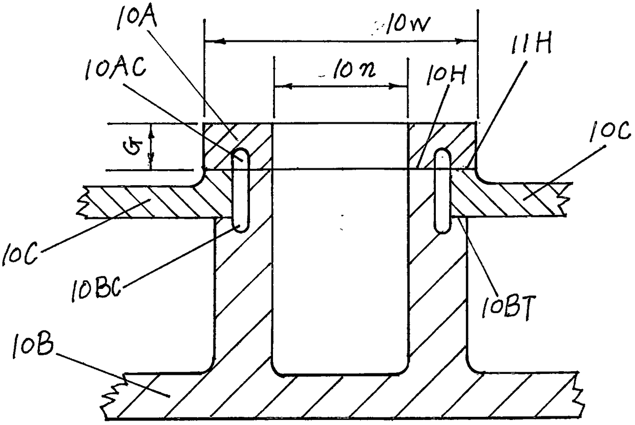
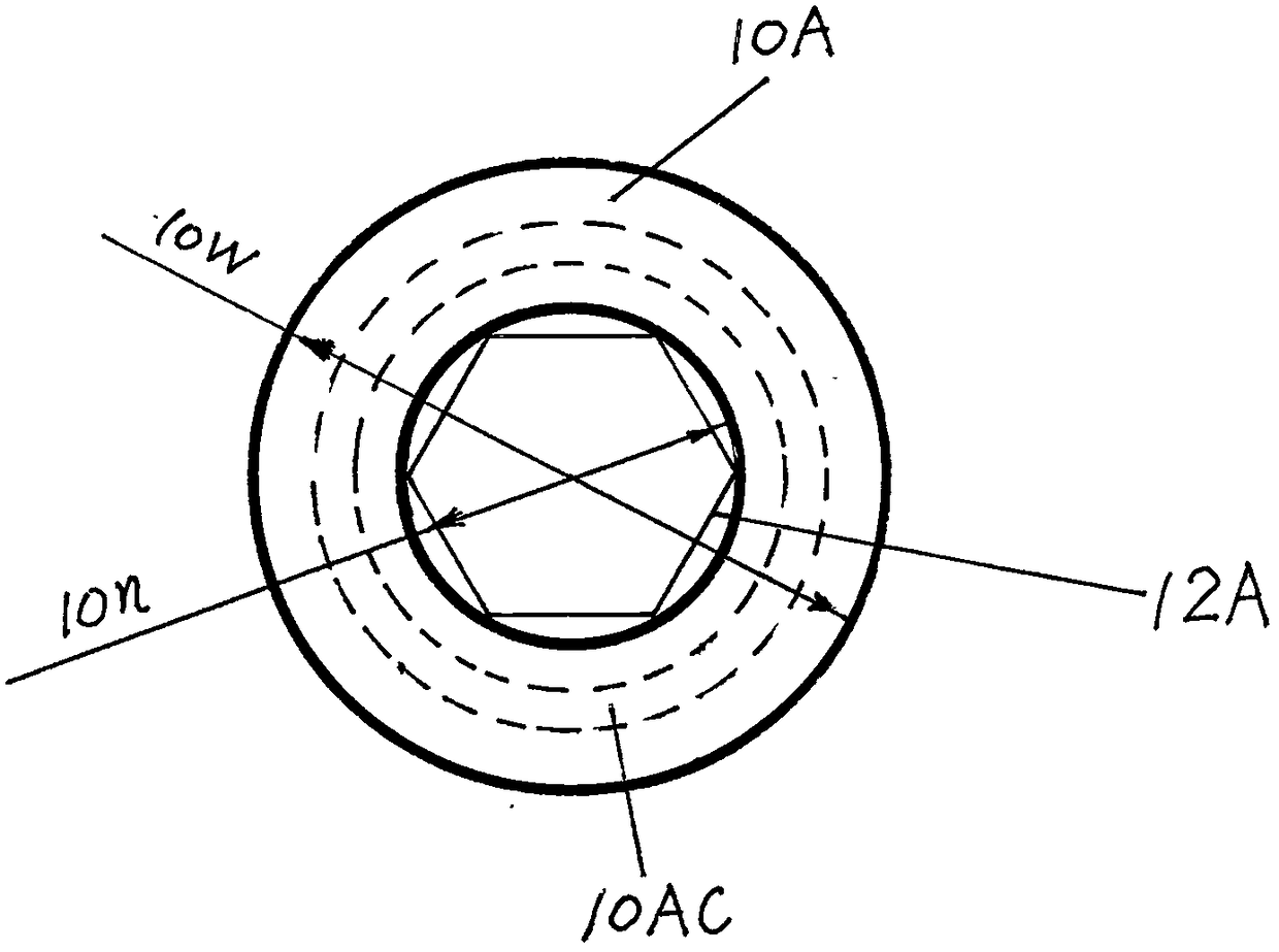
[0018] figure 1 : An embodiment of a rotational friction welding structural assembly formed by axially assembling the joints of the openings of the first workpiece and the second workpiece. The supporting surface 10BT of the first workpiece 10B supports the second workpiece 10C, and the rotary friction welding orifice connecting ring 10A rotates under the pressure of pressing the first welding interface 10H and the second welding interface 11H. As the temperature rises, the second welding interface The material at the first welding interface 10H and the second welding interface 11H is softened and pushed out of the first welding interface 10H and the second welding interface 11H, the rotation is stopped, the workpiece is cooled under pressure, and the friction welding is completed. In addition to flowing into the orifice gap between the first workpiece and the second workp...


PUM


Abstract

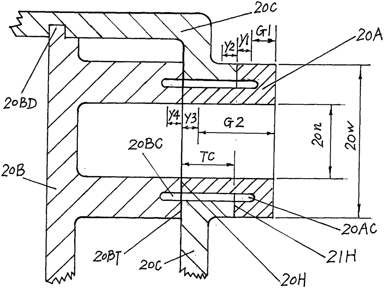
A spin friction welding structure assembly comprises a spin friction welding orifice connecting ring (20A), a first workpiece (20B) and a second workpiece (20C). The bottom of the spin friction welding orifice connecting ring (20A) is provided with a first friction welding interface (20H) in friction welding connection with the first workpiece (20B) and a second friction welding interface (21H) infriction welding connection with the second workpiece (20C). The first friction welding interface (20H) and the second friction welding interface (21H) of the bottom of the spin friction welding orifice connecting ring (20A) have a step-shaped height difference (TC). A spin friction welding extrudate containing groove (20AC) arranged between the first friction welding interface (20H) and the second friction welding interface (21H) is arranged at the bottom of the spin friction welding orifice connecting ring (20A). The spin friction welding structure assembly can be used for pressure castingof cylinder covers, cylinder cover and cylinder body combined pressure casting parts and orifice high-speed welding of various mechanical devices.

Description

technical field [0001] The invention relates to a rotary friction welding structural assembly, a water-cooled internal-combustion engine cylinder head equipped with the rotary friction welding structural assembly, a water-cooled internal-combustion engine cylinder head block casting and a mechanical device equipped with the rotary friction welding structural assembly. The invention relates to the structure and structure design of a water-cooled internal-combustion engine cylinder head and cylinder block, as well as the technology of manufacturing the cylinder head, cylinder block, and especially the combined die-casting parts of the aluminum alloy cylinder head and cylinder body by using a high-pressure die-casting process. Background technique [0002] PCT / CN2013 / 086928 discloses the structure and structure of a cross-type die-casting water-cooled internal combustion engine cylinder head (Japanese invention patent authorization certificate number 5973678); PCT / CN2014 / 094488 ...

Claims


Application Information

Patent Timeline
IPC IPC(8): B23K33/00B23K20/12F02F1/36
CPCB23K33/00B23K20/129F02F1/36
Inventor 蒋尧夫
Owner 蒋尧夫
Learn More