Automatic shoelace machine and shoe upper processing method

A processing method and technology for wearing shoelaces, applied in the direction of shoe-making machinery, footwear, clothing, etc., can solve the problems of no significant advantage in the overall operation time, inability to achieve product consistency, and inability to completely save manpower, etc. The effect of reducing operation complexity, reducing time and saving personnel costs

Active Publication Date: 2020-06-02
POU CHEN CORPORATION
View PDF8 Cites 0 Cited by
  • Summary
  • Abstract
  • Description
  • Claims
  • Application Information

AI Technical Summary

Problems solved by technology

[0005] From the above, it can be known that the jaws of the shoelace machine can only complete the threading of the shoelace hole on one side in one trip, so it takes two trips to complete the threading of the shoelace on one upper. The overall operating time of the gripper jaws does not have a significant advantage compared to manual operating time
On the other hand, as far as shoes are sold as products in shopping malls, the shoelaces of all products should be able to present a consistent cross pattern, for example: left upper right lower or right upper left lower, etc. Since the shoelaces are not completed on both sides at the same time, but in a jump-like manner, one side is worn first and then the other side is worn, so the shoelaces completed by the shoelace machine cannot reach the requirements at the time of shipment. Product Conformity Required
[0006] In addition, the alignment and alignment of the jaws of the shoelace machine when piercing shoelaces is quite dependent on the accuracy of the positioning seat moving to the predetermined position. As long as the position of the positioning seat deviates slightly, the jaws will not be able to move smoothly. When the shoelace is passed through the shoelace hole, the position of the positioning seat must be fine-tuned and corrected manually, so it is impossible to completely save the manpower required to monitor the operation of the shoelace machine from the side.

Method used


Image

  • Automatic shoelace machine and shoe upper processing method
  • Automatic shoelace machine and shoe upper processing method
  • Automatic shoelace machine and shoe upper processing method

Examples


Embodiment Construction

[0045] The present invention will be described in detail below in conjunction with the accompanying drawings and embodiments.

[0046] Before the present invention is described in detail, it should be noted that in the following description, similar components are denoted by the same numerals.

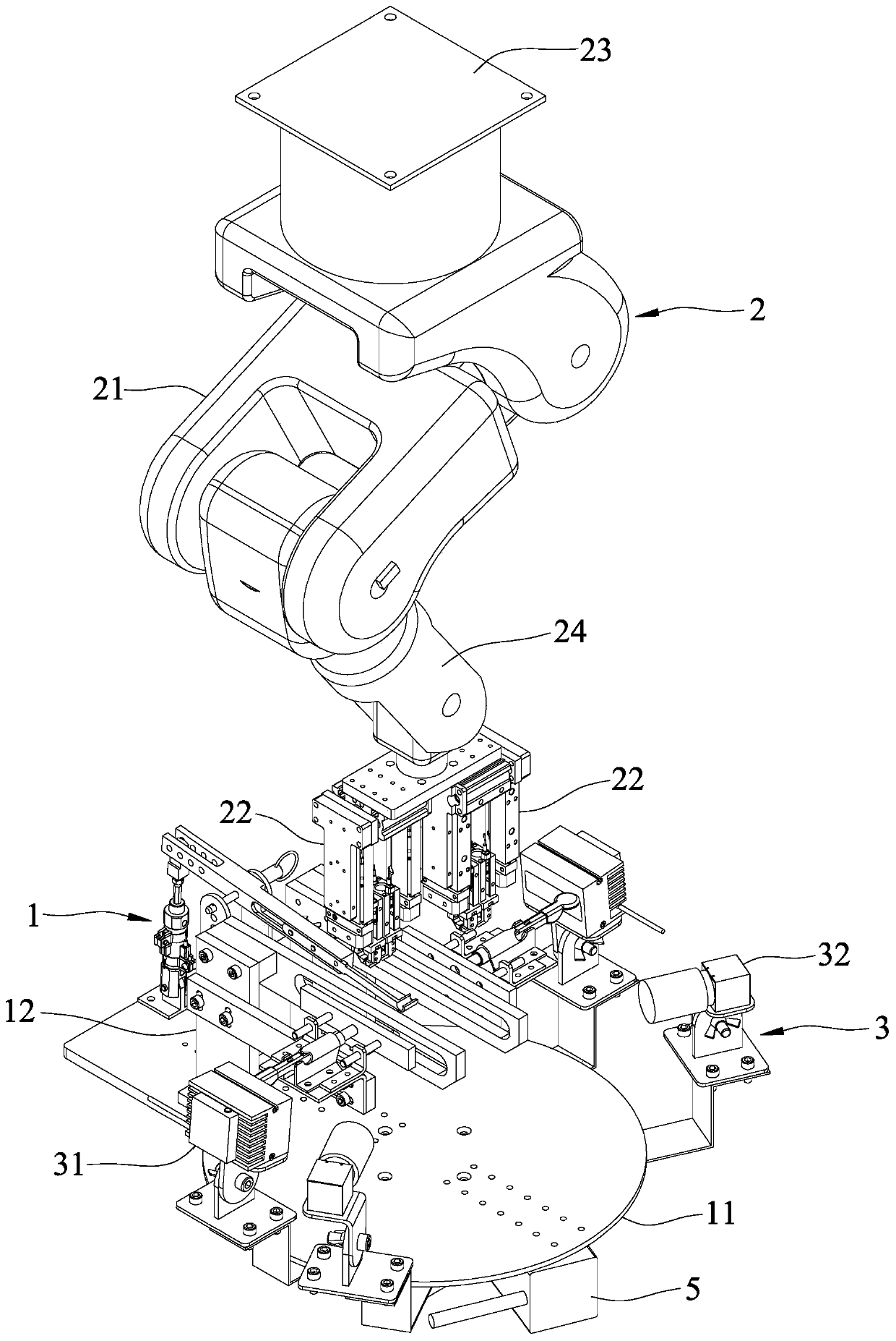
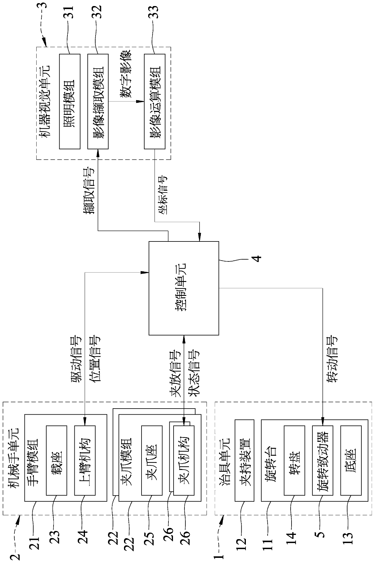
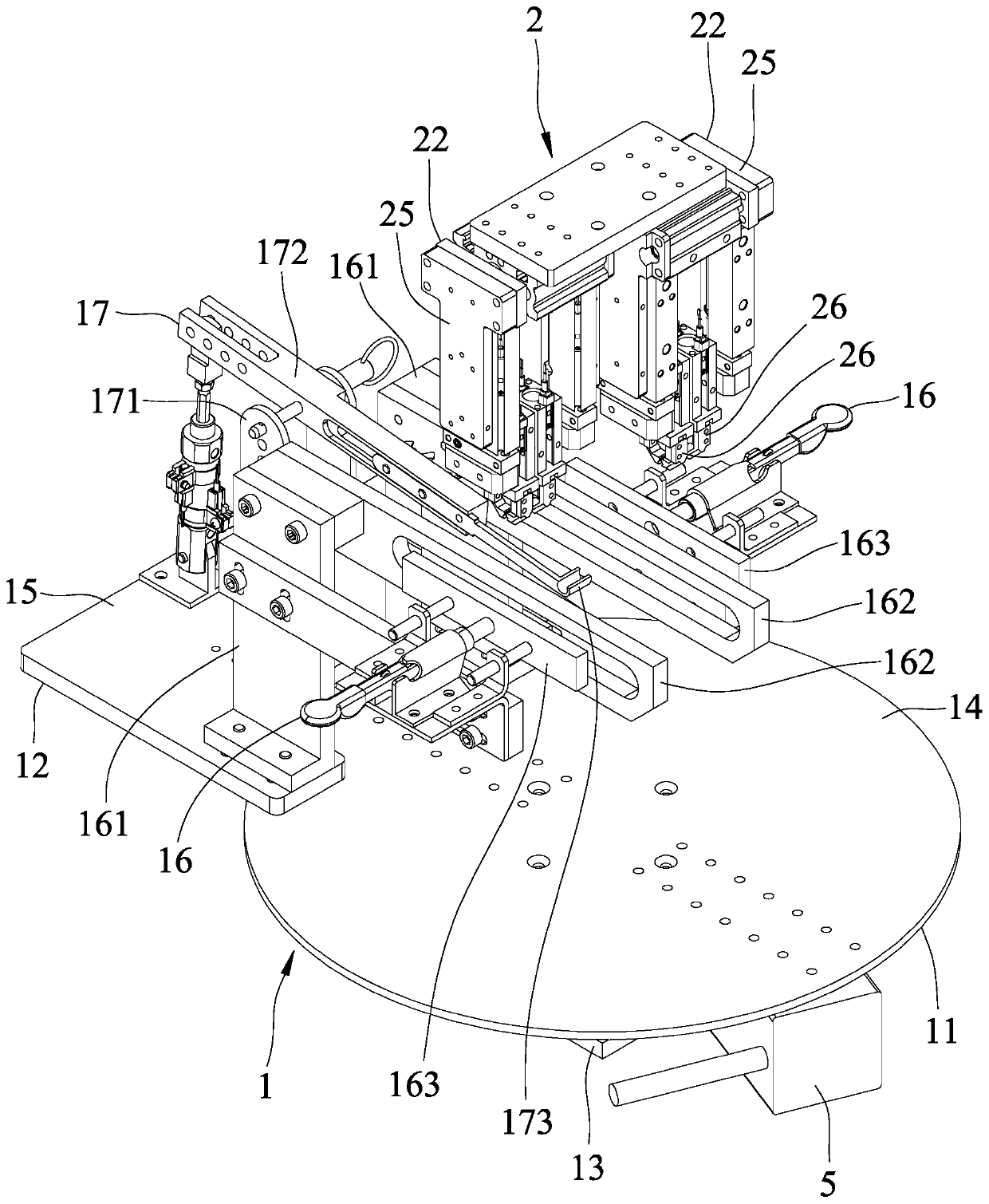
[0047] refer to figure 1 , 2 , 4, is a first embodiment of the automatic shoelace machine of the present invention, the automatic shoelace machine includes a jig unit 1, a manipulator unit 2, a machine vision unit 3 and a control unit 4, and can A shoelace 8 is worn on a vamp portion 9 .

[0048] refer to Figure 4 and Figure 5 , the shoelace 8 includes two end caps 81 and a flexible section 82 connected between the end caps 81 . The vamp portion 9 includes two shoe eyelets 91 arranged at intervals, and a shoe tongue 92 located between the shoe eyelets 91 . Each shoe eyelet 91 has a plurality of shoelace holes 93 arranged through and arranged at intervals. The tongue 92 has a r...


PUM


Abstract

The invention provides an automatic shoelace tying machine and a vamp processing method. According to the automatic shoelace tying machine, a shoelace can penetrate into a vamp part. The shoelace comprises two end coating parts and a flexible section. The vamp part comprises two eyelet pieces with multiple shoelace holes. The automatic shoelace tying machine comprises a jig unit, a mechanical handunit, a machine vision unit and a control unit. The jig unit is arranged on the vamp part. The mechanical hand unit can clamp or release the end coating parts at the same time and enable the end coating parts to sequentially penetrate through the shoelace holes. The machine vision unit can detect the positions of the shoelace holes and output a coordinate signal related to the position of one ofthe shoelace holes. The control unit receives the coordinate signal and outputs a drive signal for controlling the mechanical hand unit to act. By means of the automatic shoelace tying machine, the processing time of automatic shoelace tying can be shortened, and the acting complexity of the mechanical hand unit can be reduced.

Description

technical field [0001] The invention relates to an automatic processing machine and a processing method, in particular to an automatic shoelace threading machine and a shoe upper processing method used in the shoe manufacturing process. Background technique [0002] Generally speaking, in order to facilitate consumers to wear shoes directly after purchasing, a processing procedure for wearing shoelaces is added to the shoe making process. Because the processing of wearing shoelaces by manual operation is quite labor-intensive, so now a kind of automatic shoelace-wearing machine has been developed, such as the patent case of Chinese Authorized Notice No. CN103876393. [0003] The shoelace machine is used to thread a shoelace on a shoe upper without a sole, and the shoelace machine includes a frame, a positioning seat that can move back and forth relative to the frame and is fixedly arranged for the shoe upper, A boom that can clamp the shoe upper and position the shoe upper ...

Claims


Application Information

Patent Timeline
Patent Type & Authority Patents(China)
IPC IPC(8): A43D8/00
CPCA43D8/00
Inventor 杨育峰张文堡柯昭全王耀鑫许千昱
Owner POU CHEN CORPORATION
Why Eureka
Try Eureka