
Machine vision light source

A machine vision and light source technology, applied in the field of vision, can solve the problems of low efficiency and unsatisfactory effect, and achieve the effect of ideal effect and high light source shaping efficiency.

Inactive Publication Date: 2018-09-21
SHENZHEN GONGJIN ELECTRONICS CO LTD
View PDF5 Cites 2 Cited by
  • Summary
  • Abstract
  • Description
  • Claims
  • Application Information

AI Technical Summary

Problems solved by technology

[0003] The purpose of the present invention is to provide a machine vision light source, which aims to solve the technical problem of low efficiency and unsatisfactory effect of the light source in the prior art because it needs rich experience and multiple testing experiments to finalize the shape

Method used


Image

  • Machine vision light source
  • Machine vision light source
  • Machine vision light source

Examples


Embodiment Construction

[0022] In order to make the object, technical solution and advantages of the present invention clearer, the present invention will be further described in detail below in conjunction with the accompanying drawings and embodiments. It should be understood that the specific embodiments described here are only used to explain the present invention, not to limit the present invention.

[0023] It should be noted that when a component is referred to as being “fixed on” or “disposed on” another component, it may be directly or indirectly on the other component. When an element is referred to as being "connected to" another element, it can be directly or indirectly connected to the other element.

[0024] The orientation or positional relationship indicated by the terms "upper", "lower", "left", "right", etc. are based on the orientation or positional relationship shown in the drawings, and are for convenience of description only, rather than indicating or implying the referred devic...


PUM


Abstract

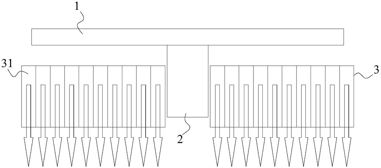
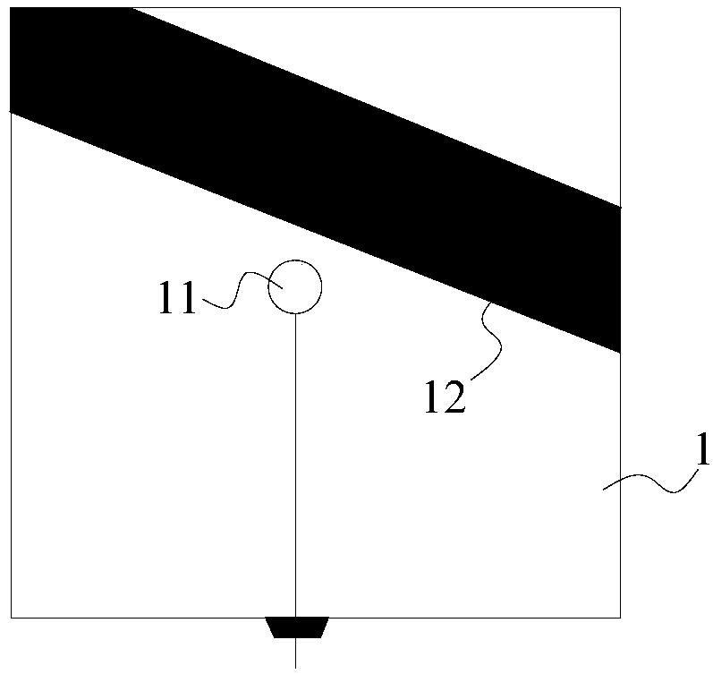
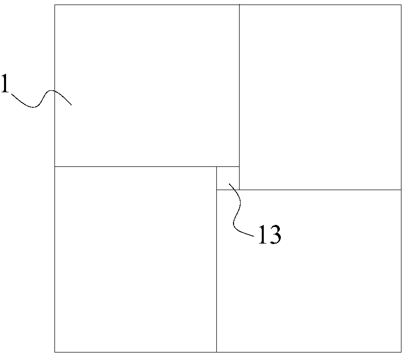
The invention is suitable for the technical field of vision, and provides a machine vision light source comprising a displayer, a camera which is arranged in the central area of the displayer and a cellular board which is arranged on the front side of the displayer and surrounds the camera. Compared with the light sources in the prior art, the displayer is arranged and the camera is arranged in the central area of the displayer, and the cellular board is arranged on the front side of the displayer and surrounds the camera so that the machine vision light source is enabled to become a type of general light source equipment and cope with multiple occasions requiring using the light source, the light source formation efficiency is high and the effect is ideal, and the parallel light source can be realized without meticulously designing the light reflection lid or calculating the focus and other tedious schemes.

Description

technical field [0001] The invention belongs to the field of vision technology, in particular to a machine vision light source. Background technique [0002] In the prior art, a good light source is the prerequisite for the realization of machine vision. According to various influences such as the test object, test target, test environment and lens, each test will have several best matching light sources. Among them, good The light source can greatly improve the recognition efficiency and reduce the difficulty of the visual recognition algorithm. However, selecting the best matching light source not only requires rich experience, but also needs to go through many tests and experiments to finalize the shape. This method of finalizing the light source is not only inefficient, but also the effect of the selected light source is not ideal. Therefore, it is necessary to develop a general light source device, which can cope with various occasions where light sources are required....

Claims


Application Information

Patent Timeline
Patent Type & Authority Applications(China)
IPC IPC(8): G03B15/03G03B15/06H04N5/225G03B15/05
CPCG03B15/03G03B15/06H04N23/57
Inventor 金志虎汪澜王宏
Owner SHENZHEN GONGJIN ELECTRONICS CO LTD
Learn More