


Quick Research
Generate reliable direction feasibility study reports for your R&D in just a few steps.

Technical Q&A
Discover and master advanced knowledge NOW. Basics, ideas, possibilities, all at once.

Find Solutions
As an expert in R&D theories, this can generate solutions to your technical problems instantly.

Evaluate Feasibility
Analyze your overall solution with one click, know your potential R&D risks in advance.

Monitor Landscape
Get weekly tech updates, stay abreast of the latest tech innovations and key insights.
Water passage control device and local cleaning device
A waterway control and waterway technology, which is applied to water supply devices, flushing equipment with water tanks, sanitary equipment for toilets, etc., can solve the problem of high manufacturing cost of local cleaning devices, complicated waterway control, and local cleaning devices cannot be flushed, etc. problems, to achieve the effect of reducing product cost and requirements for power modules, simple and reliable structure, and avoiding mechanical wear
- Summary
- Abstract
- Description
- Claims
- Application Information
AI Technical Summary
Problems solved by technology
Method used
Image

Examples
Embodiment 1
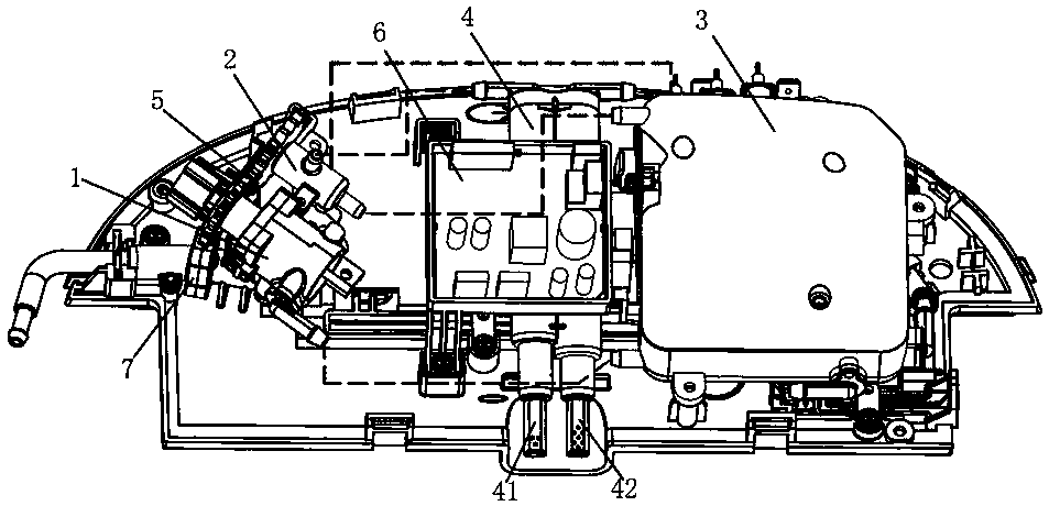
[0049] Such as Figure 1-4 As shown, the local cleaning device of the present invention includes a throttle valve 7 , a control valve group 1 , a heating assembly 3 , a linkage mechanism 5 , a control assembly 6 and a flushing assembly 4 . Throttle valve 7 is set at the forefront of the waterway to stabilize the pressure and limit the flow, so as to ensure the stability of the product under different working water pressures. The heating assembly 3 may consist of a hot water tank for heating and storing water flowing therein, but is not limited thereto. The heating element 3 can also be instant heating, and the heating element 3 can quickly heat the inflowing water when the water flows through it. The control assembly 6 is used to control the heating assembly 3 . The flushing assembly 4 is provided with at least two flushing water channels, which are respectively connected to the buttock washing nozzle 41 and the women's washing nozzle 42, and uses heated water to clean the h...
Embodiment 2
[0059] The main difference between the present embodiment and the first embodiment lies in the linkage structure, the first driving part 10 and the second driving part 20 are linked by magnetic force.
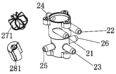
[0060] Such as Figure 5-6 As shown, in this embodiment, the control valve group 1 has a first cold water inlet 11, a first cold water outlet 12, and a first drive unit 10 for controlling the connection between the first cold water inlet 11 and the first cold water outlet 12, The first cold water outlet 12 is connected to the water inlet end of the heating assembly 3 . The control valve group 1 also has a hot water inlet 23, a first hot water outlet 25, a second hot water outlet 26, and a second hot water outlet 23 for selectively connecting the two hot water outlets 25, 26. The driving part 20 and the hot water inlet 23 are connected to the water outlet of the heating assembly 3 , and the first hot water outlet 25 and the second hot water outlet 26 are respectively connected ...
Embodiment 3
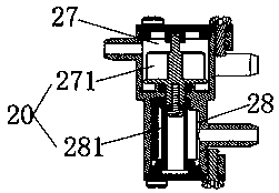
[0067] The main difference between this embodiment and Embodiment 1 lies in the linkage mode, the first driving part and the second driving part are linked through hydraulic pressure.
[0068] Such as Figure 7-10 As shown, the control valve group 1 has the first cold water inlet 11, the first cold water outlet 12, the second cold water outlet 13 and the first cold water inlet 11 to selectively connect the two cold water outlets 12, 13. drive unit 10. The control valve group 1 also has a hydraulic reversing mechanism, the hydraulic reversing mechanism has a first cavity 27 and a second cavity 28, the first cavity 27 is provided with a second cold water inlet 21, a third cold water inlet 22, The third cold water outlet 24, the second cavity 28 is provided with a hot water inlet 23 and a first hot water outlet 25, a second hot water outlet 26, the second cold water inlet 21 communicates with the first cold water outlet 12, The third cold water inlet 22 is in communication with...
PUM
 Abstract
Description
Claims
Application Information
 - R&D Engineer
- R&D Manager
- IP Professional
- Industry Leading Data Capabilities
- Powerful AI technology
- Patent DNA Extraction
Browse by: Latest US Patents, China's latest patents, Technical Efficacy Thesaurus, Application Domain, Technology Topic, Popular Technical Reports.
© 2024 PatSnap. All rights reserved.Legal|Privacy policy|Modern Slavery Act Transparency Statement|Sitemap|About US| Contact US: help@patsnap.com