Fall prevention lifting device and fall prevention method thereof
A lifting device and anti-fall technology, applied in the direction of lifting device, lifting frame, etc., can solve the problems of non-continuous production, bearing nut sliding wire, etc., and achieve the effect of strong versatility, avoidance of jamming, and ingenious concept.
- Summary
- Abstract
- Description
- Claims
- Application Information
AI Technical Summary
Problems solved by technology
Method used
Image

Examples
Embodiment 1
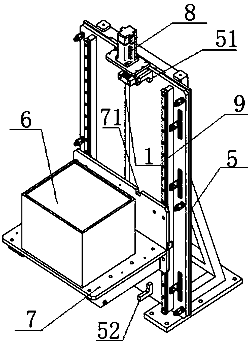
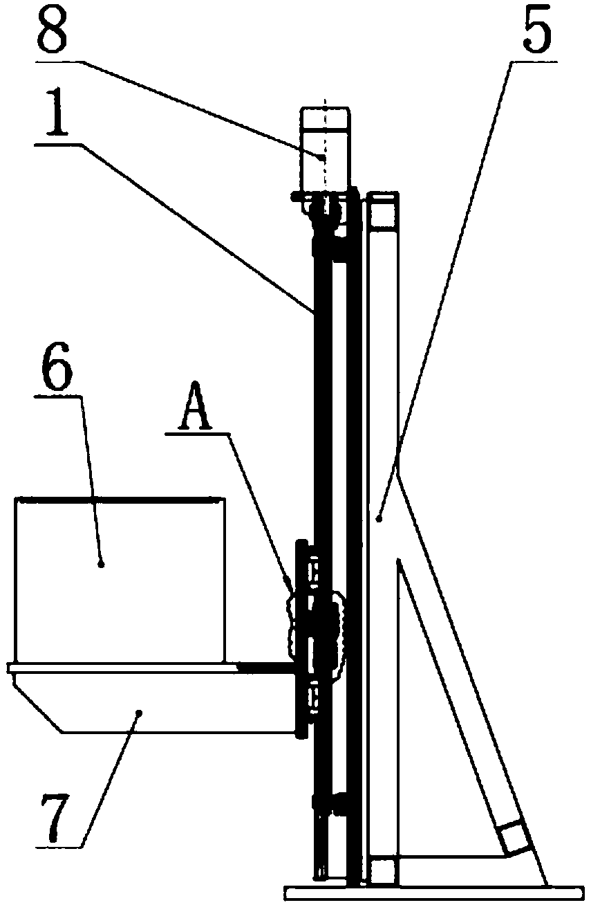
[0051] The anti-fall lifting device of the present embodiment, such as figure 1 , 2 , shown in 3 and 4, including frame 5, lifting platform 7 and power mechanism 8, is characterized in that, also comprises double-nut screw mechanism, and described double-nut screw mechanism comprises screw mandrel 1 and is sleeved on screw mandrel 1 successively The main nut 2 and the auxiliary nut 4, wherein: the two ends of the screw rod 1 are connected to the power mechanism 8 in transmission type, and the power mechanism 8 is fixed on the frame 5; the main nut 2 is sleeved on the nut seat along the outer wall 24, the nut seat 24 is fixedly connected with the lifting platform 7; a gap is reserved between the bottom end of the main nut 2 and the auxiliary nut 4, which can avoid the load bearing of the auxiliary nut 4, the main nut 2 is load bearing, and the auxiliary nut 4 is not load bearing ; When the sliding wire between the main nut 2 and the lead screw 1 fails, the main nut 2 is slid by ...
Embodiment 2
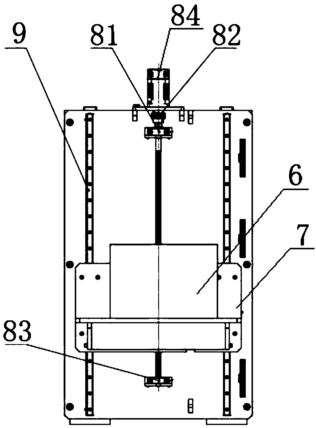
[0054] The anti-fall lifting device of this embodiment has the same basic structure as that of Embodiment 1, and the improvements are as follows: figure 2 As shown, the power mechanism 8 includes an upper bearing block 81, a shaft coupling 82, a lower bearing block 83 and a motor 84; the motor 84 is fixed on the upper beam of the frame 5, and is connected with the screw mandrel 1 through the shaft coupling 82, so that The upper bearing seat 81 and the lower bearing seat 83 are respectively fixed on the upper part and the lower part of the frame 5, and are socketed with the two ends of the screw rod 1, so as to realize the purpose of continuous lifting.
Embodiment 3
[0056] The basic structure of the anti-fall lifting device of this embodiment is the same as that of Embodiment 2. The improvement is that the bottom end of the main nut 2 is provided with symmetrical protrusions 22, and the protrusions 22 can be one or more, such as Figure 5 , 7 , 8, 9, and 10, there are 2 in this embodiment, such as Figure 5 , 11 , 12, 13, and 14, the top of the auxiliary nut 4 is provided with a card groove 41 and a card platform 42 corresponding to the card protrusion 22, and there are also two, and the card protrusion 22 and the card platform 42 are simply overlapped, and the main Before the nut 2 slides the wire, the card protrusion 22 and the card table 42 are overlapped together after a little contact, and the main nut 2 can drive the auxiliary nut 4 to move up and down with the screw 1; when the wire between the main nut 2 and the screw 1 fails Finally, because the main nut 2 bears the weight and adds its own gravity, it will slide down to the aux...
PUM
 Abstract
Description
Claims
Application Information
 - Generate Ideas
- Intellectual Property
- Life Sciences
- Materials
- Tech Scout
- Unparalleled Data Quality
- Higher Quality Content
- 60% Fewer Hallucinations
Browse by: Latest US Patents, China's latest patents, Technical Efficacy Thesaurus, Application Domain, Technology Topic, Popular Technical Reports.
© 2025 PatSnap. All rights reserved.Legal|Privacy policy|Modern Slavery Act Transparency Statement|Sitemap|About US| Contact US: help@patsnap.com