Locked-rotor, overload, phase-loss and free-burning motor of high-efficiency and energy-saving water pump

A high-efficiency energy-saving and water pump technology, which is applied in the field of lack of burning motors, high-efficiency energy-saving water pumps, and overload fields. It can solve the problems of large motor damage and easy motor burnout, and achieve the effect of avoiding motor burnout and winding temperature.

Pending Publication Date: 2018-09-18
TAIZHOU SHUANGLONG PUMP IND
View PDF0 Cites 2 Cited by
  • Summary
  • Abstract
  • Description
  • Claims
  • Application Information

AI Technical Summary

Problems solved by technology

[0004] The existing protector is a contact separation type of dynamic and static contact pieces. When overload or phase loss occurs, the current increases sharply, and the moving contact piece on the protector is heated and deformed, and is separated from the static contact piece, thereby disconnecting the circuit and stopping the motor. However, after a period of time when the moving contact piece cools down, the moving contact piece resumes its deformation and closes with the static contact piece again, the motor restarts, and the moving contact piece is disconnected from the static contact piece due to heat deformation, so that the start and stop of the motor will be repeated, which cannot solve the problem At the same time, it will do a lot of damage to the motor, and it is easy to burn the motor

Method used


Image

  • Locked-rotor, overload, phase-loss and free-burning motor of high-efficiency and energy-saving water pump
  • Locked-rotor, overload, phase-loss and free-burning motor of high-efficiency and energy-saving water pump
  • Locked-rotor, overload, phase-loss and free-burning motor of high-efficiency and energy-saving water pump

Examples


Embodiment approach

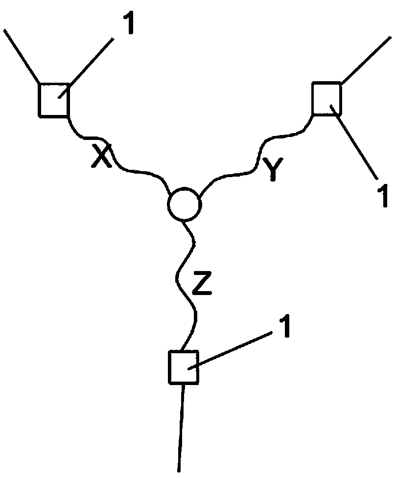
[0023] Such as figure 2 As shown, it is the second embodiment of the present invention, a high-efficiency energy-saving water pump stall, overload, phase loss and non-burning motor, including three-phase windings X, Y, Z with delta connection, and its rated power is less than 7.5 kW, a protector 1 is arranged in series on the windings X, Y, and Z of each phase, and its structure is the same as that of the protector in Embodiment 1.

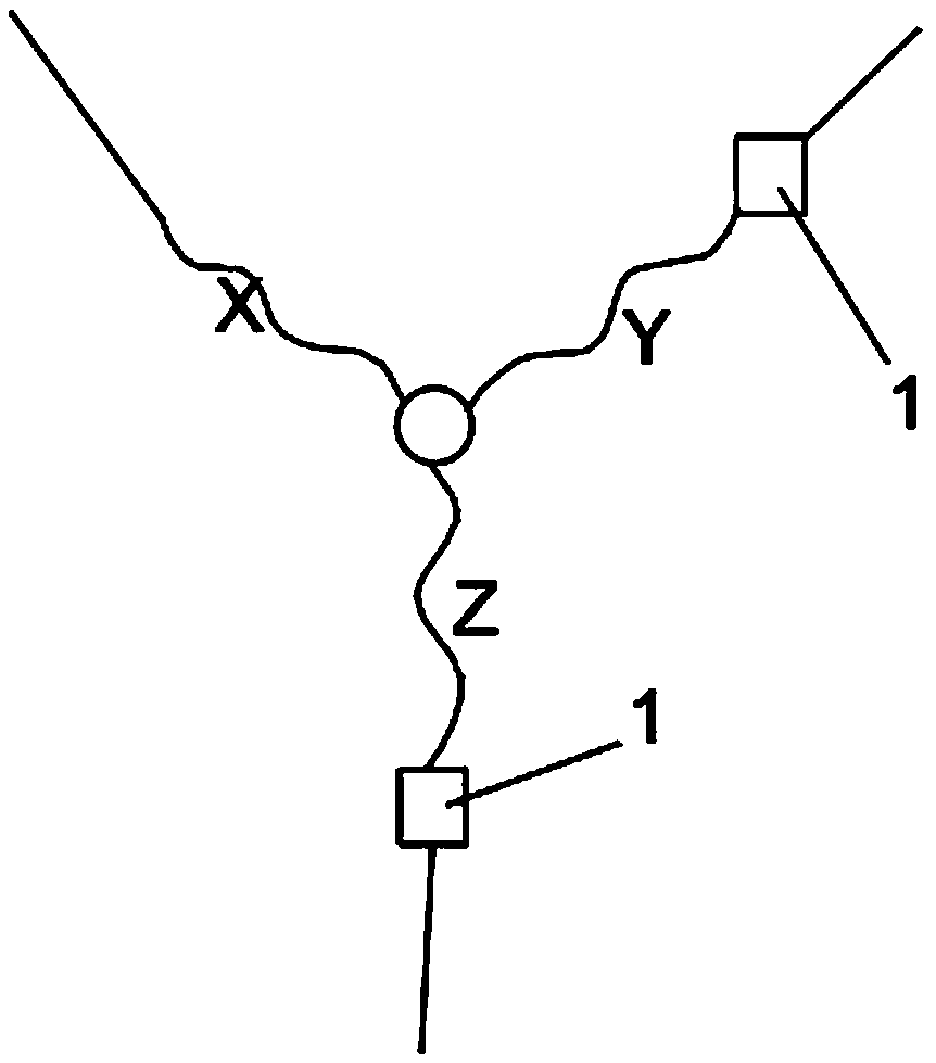
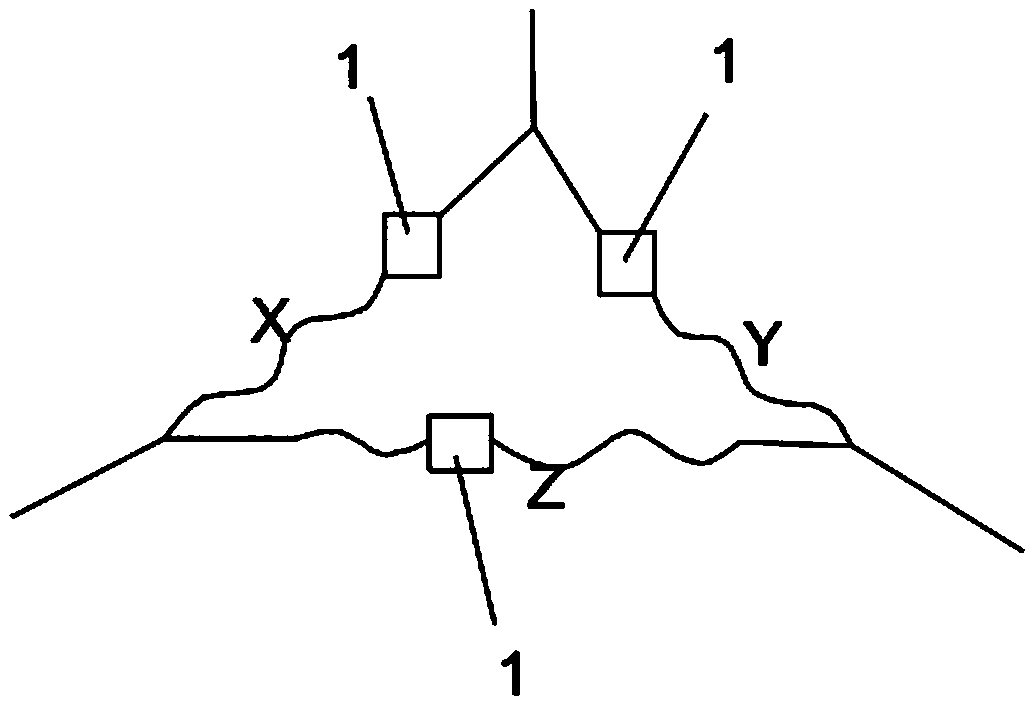
[0024] Such as image 3 As shown, it is the third embodiment of the present invention, a high-efficiency energy-saving water pump stall, overload, phase loss and non-burning motor, including three-phase windings X, Y, Z with delta connection, and its rated power is less than 7.5 kW, a protector 1 is arranged in series on the two phases of the windings X, Y, and Z of each phase, and its structure is the same as that of the protector in Embodiment 1.

[0025] Such as Figure 4 to Figure 6 As shown, the protector 1 includes a moving contact pie...


PUM


Abstract

According to the technical scheme provided by the invention, a locked-rotor, overload, phase-loss and free-burning motor of a high-efficiency and energy-saving water pump is provided. The motor comprises a three-phase winding. The motor is characterized in that at least two phases of the three-phase winding are respectively provided with a protector. The protector comprises a movable contact pieceand a static contact piece. The movable contact piece is in contact with the static contact piece when the temperature of the movable contact piece is lower than a preset temperature. The movable contact piece is separated from the static contact piece when the temperature of the movable contact piece is higher than the preset temperature. A movable contact piece binding post is arranged at the tail part of the movable contact piece. A static contact piece binding post is arranged at the tail part of the static contact piece. A heating resistor is connected below the static contact piece in parallel. The heating resistor is insulated and isolated from the static contact piece. The two ends of the heating resistor are connected to the static contact piece binding post and the movable contact piece binding post respectively. The damage phenomenon of the motor is effectively avoided. The protector is low in price and economical in cost.

Description

technical field [0001] The invention relates to a motor for a submersible pump, in particular to a high-efficiency and energy-saving water pump stall, overload, phase-lack and non-burning motor. Background technique [0002] The submersible pump motor often adopts a three-phase asynchronous motor. Its operation is to use three-phase alternating current to pass into the three-phase winding of the motor to generate a rotating magnetic field in the stator cavity. The rotor conductor relatively cuts the magnetic field lines of the magnetic field to generate the rotational motion of the rotor. Make the motor spin up. [0003] In practice, in order to ensure the safe operation of the motor, the motor has short-circuit protection and overload protection devices, so that when a fault occurs, the power supply is automatically cut off to protect the motor and power supply lines. [0004] The existing protector is a contact separation type of dynamic and static contact pieces. When ov...

Claims


Application Information

Patent Timeline
IPC IPC(8): H02K3/28H02K11/20H02H7/085H02H7/09
CPCH02H7/085H02H7/09H02K3/28H02K11/20
Inventor 杨昌正
Owner TAIZHOU SHUANGLONG PUMP IND
Why Eureka
Try Eureka