
Dual-frequency dual-mode gyrotron traveling wave tube input coupler

An input coupling, circular waveguide technology, applied in the field of gyroscopic traveling wave tube input couplers, can solve problems such as single-frequency operation of the input coupler

Active Publication Date: 2018-09-18
UNIV OF ELECTRONIC SCI & TECH OF CHINA
View PDF2 Cites 7 Cited by
  • Summary
  • Abstract
  • Description
  • Claims
  • Application Information

AI Technical Summary

Problems solved by technology

[0004] In order to solve the problem that the TWT input coupler can only work in a single frequency band, the present invention proposes a new TWT dual-band (Ku / Ka) dual-mode (TE11 / TE01) input coupler

Method used


Image

  • Dual-frequency dual-mode gyrotron traveling wave tube input coupler
  • Dual-frequency dual-mode gyrotron traveling wave tube input coupler
  • Dual-frequency dual-mode gyrotron traveling wave tube input coupler

Examples


Embodiment Construction

[0019] Below in conjunction with a dual-band (Ku / Ka band) input coupler design example and accompanying drawings of the double-working mode (TE11 / TE01 mode) the present invention is further elaborated:

[0020] Input signal mode: rectangular waveguide TE10 mode;

[0021] Working band 1 / frequency 1 / mode 1: Ku / 15.5GHz-18.5GHz / TE11

[0022] Working band 2 / frequency 2 / mode 2: Ka / 32GHz-36GHz / TE01

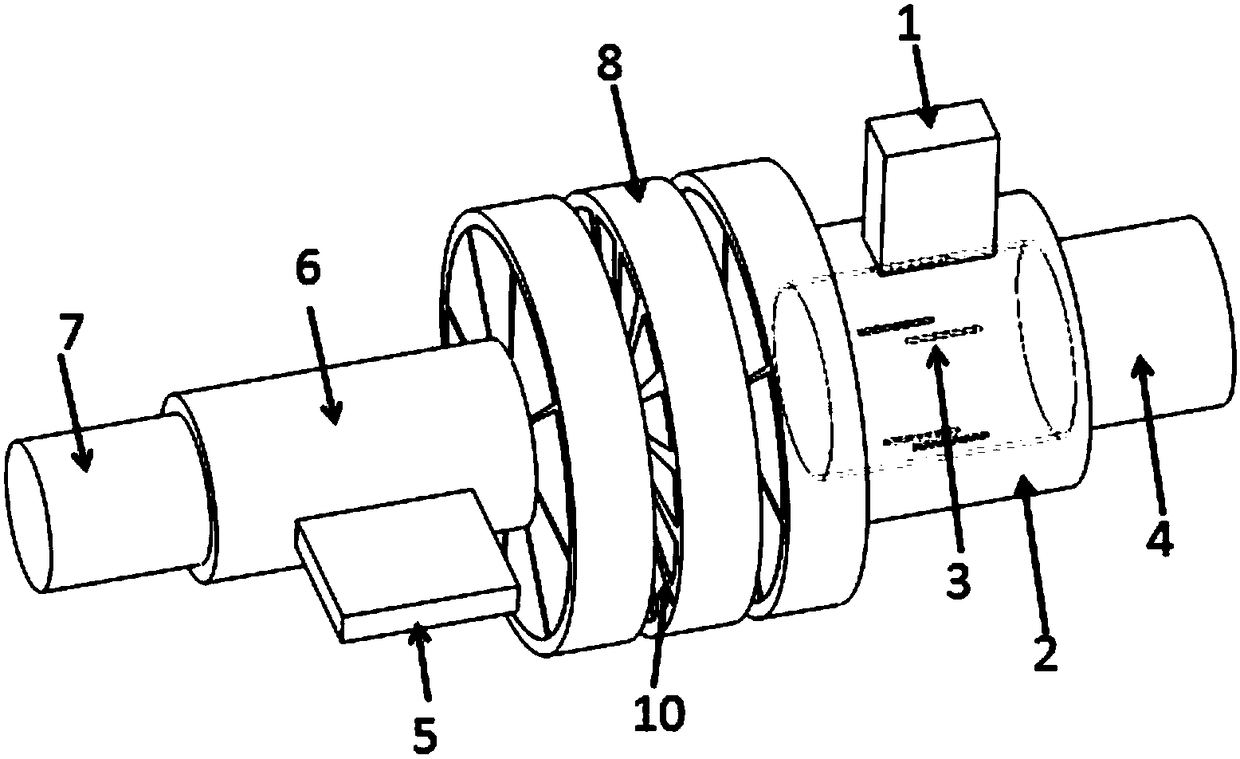
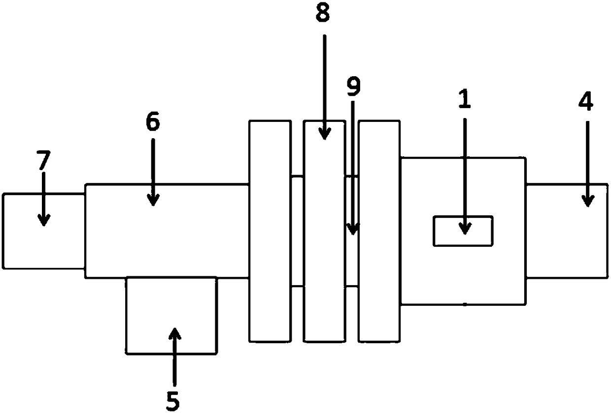
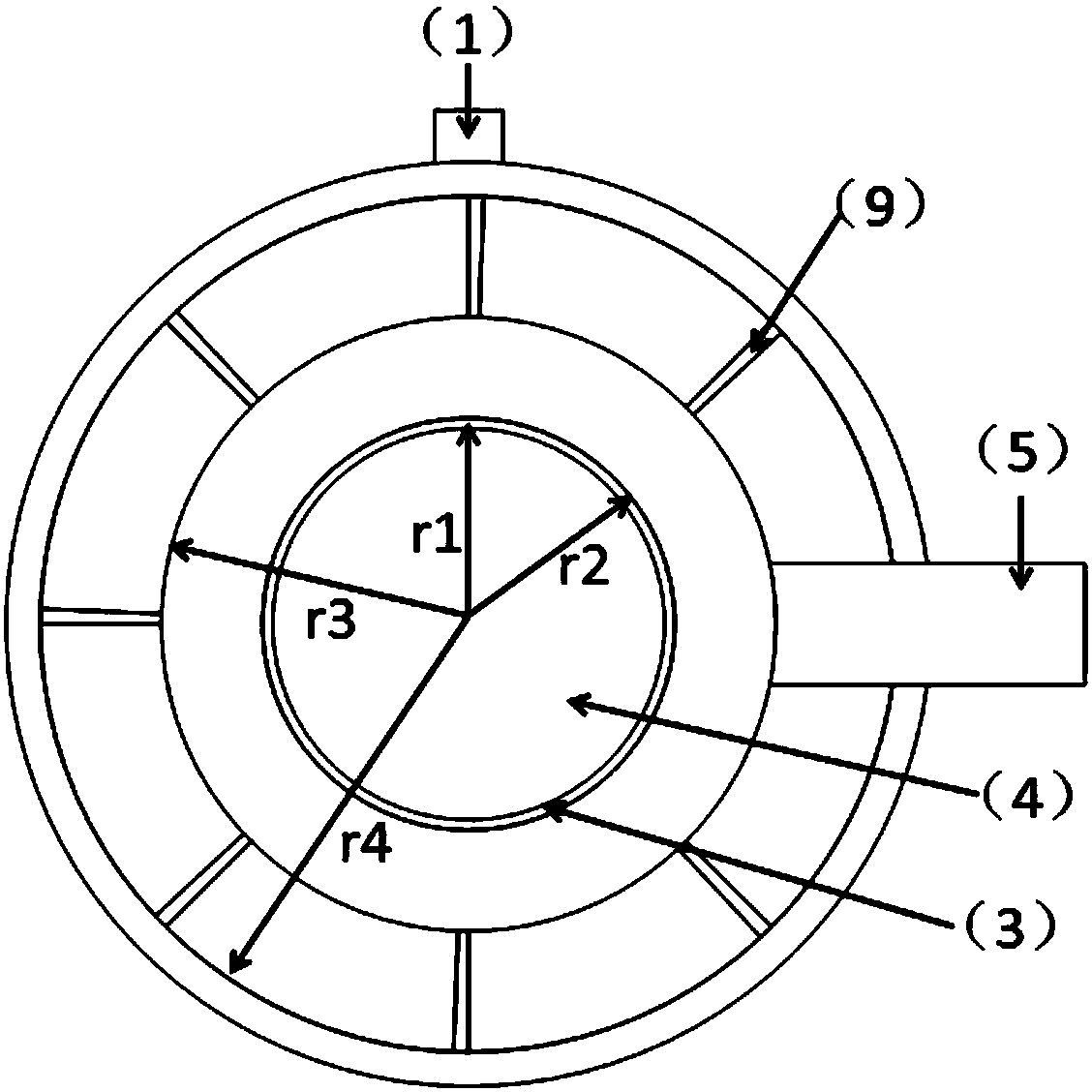
[0023] attached figure 1 It is a schematic diagram of a new dual-frequency dual-mode input coupler; figure 2 Side view of the new dual-band dual-mode input coupler; attached image 3 Top view of the new dual-band dual-mode input coupler. The invention includes: a TE11-mode input coupler working in the Ku band, a TE01-mode input coupler working in the Ka band, and a mode-selective cascaded reflection cavity between the two.

[0024] Among them, the TE01 mode input coupler working in the Ka band:

[0025] The first input rectangular waveguide (1): adopt the standard rectangular wave...


PUM


Abstract

The invention discloses a dual-frequency dual-mode gyrotron traveling wave tube input coupler, which relates to the technical field of microwave and millimeter wave devices, in particular to a gyrotron traveling wave tube input coupler. The dual-frequency dual-mode gyrotron traveling wave tube input coupler is implemented by adopting the technical measures that the structure of the dual-band (Ku / Ka-band) dual-working-mode (TE11 / TE01-mode) input coupler comprises three main parts including a TE11-mode input coupler operating in the Ku band, a TE01-mode input coupler operating in the Ka band, and a cascade reflection cavity structure having a mode selecting property, thereby realizing the purpose of the invention. Compared with the traditional input coupler, the input coupler disclosed by the invention can operate both in the Ku and the Ka band; by adopting the cascade reflection cavity structure, thus total reflection of the TE01 mode is realized, and the single-direction output of theTE10 mode by means of an output circular waveguide is guaranteed; and by adopting a vane loading attenuation material, a competitive mode of attenuating the TE01 mode is achieved.

Description

technical field [0001] The invention relates to the technical field of microwave and millimeter wave devices, in particular to an input coupler for a gyrotron traveling wave tube. Background technique [0002] The cyclotron traveling wave tube is a high-power, wide-band microwave and millimeter-wave amplifier with high power and wide-band characteristics. It has very important application prospects in the fields of millimeter-wave imaging radar, millimeter-wave communication systems, and electronic warfare. Therefore, Internationally respected. Some modern advanced radars and electronic countermeasures can effectively work in a wide frequency band, and even work across frequency bands, so it is often necessary to use several gyrotrons as microwave sources, which is not conducive to reducing the size of the entire system. And increase the cost of the whole equipment. Therefore, the gyrotron TWT that can work in multiple frequency bands at the same time has very important ap...

Claims


Application Information

Patent Timeline
IPC IPC(8): H01J23/38
CPCH01J23/38
Inventor 徐勇孙淼彭廷会李洋王兆栋罗勇
Owner UNIV OF ELECTRONIC SCI & TECH OF CHINA
Learn More