
Coaxial wire-feeding cladding head for laser metal printing

A coaxial wire feeding and welding head technology, applied in laser welding equipment, metal processing equipment, welding equipment, etc., can solve the problems of bad influence of parts forming, bending of metal wire, unstable forming process, etc., and achieve compact structure of the device , Improve stability, reduce the effect of convergence angle

Pending Publication Date: 2018-09-18
SHANGHAI IND TECH INST
View PDF1 Cites 8 Cited by
  • Summary
  • Abstract
  • Description
  • Claims
  • Application Information

AI Technical Summary

Problems solved by technology

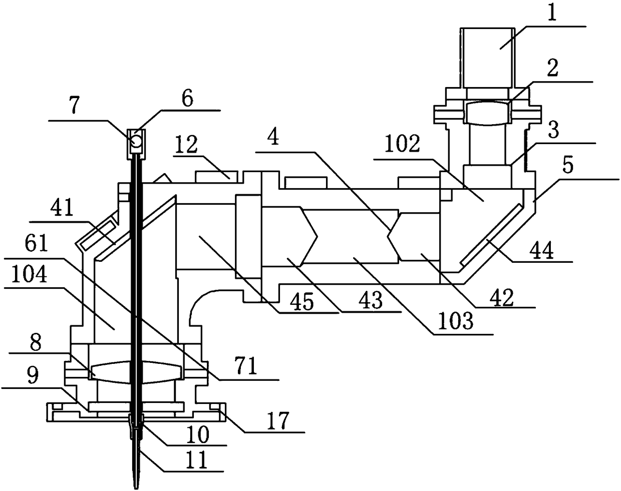
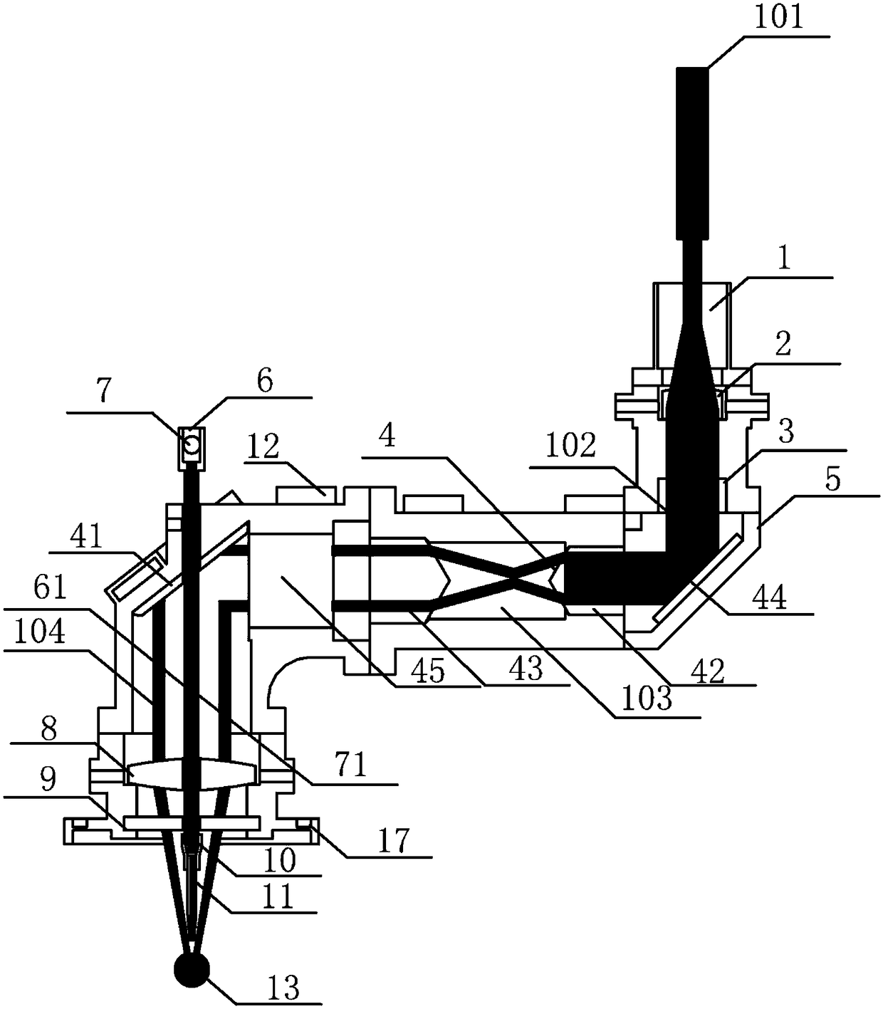
However, this coaxial wire feeding welding head has two disadvantages: 1) After the laser is transformed into a circular beam, the beam convergence angle is too large when refocusing. Therefore, the thermal effect of the metal wire during the forming process changes greatly, resulting in The process is unstable; 2) Since the metal wire is fed from the side of the welding head and sent out from the nozzle after being bent, the bending process will easily cause the metal wire to bend when it leaves the nozzle, thus affecting the synchronization between the metal wire and the ring laser. Axiality, which has adverse effects on the forming of parts

Method used


Image

  • Coaxial wire-feeding cladding head for laser metal printing
  • Coaxial wire-feeding cladding head for laser metal printing
  • Coaxial wire-feeding cladding head for laser metal printing

Examples


Embodiment Construction

[0054] The specific implementation manners of the present invention will be described in further detail below in conjunction with the accompanying drawings. These embodiments are only used to illustrate the present invention, not to limit the present invention.

[0055] In the description of the present invention, it should be noted that the orientation or positional relationship indicated by the terms "inner", "outer" and the like are based on the orientation or positional relationship shown in the drawings, and are only for the convenience of describing the present invention and simplifying the description. It is not intended to indicate or imply that the referred device or element must have a particular orientation, be constructed in a particular orientation, and operate in a particular orientation, and thus should not be construed as limiting the invention.

[0056] In the description of the present invention, it should be noted that unless otherwise specified and limited,...


PUM


Abstract

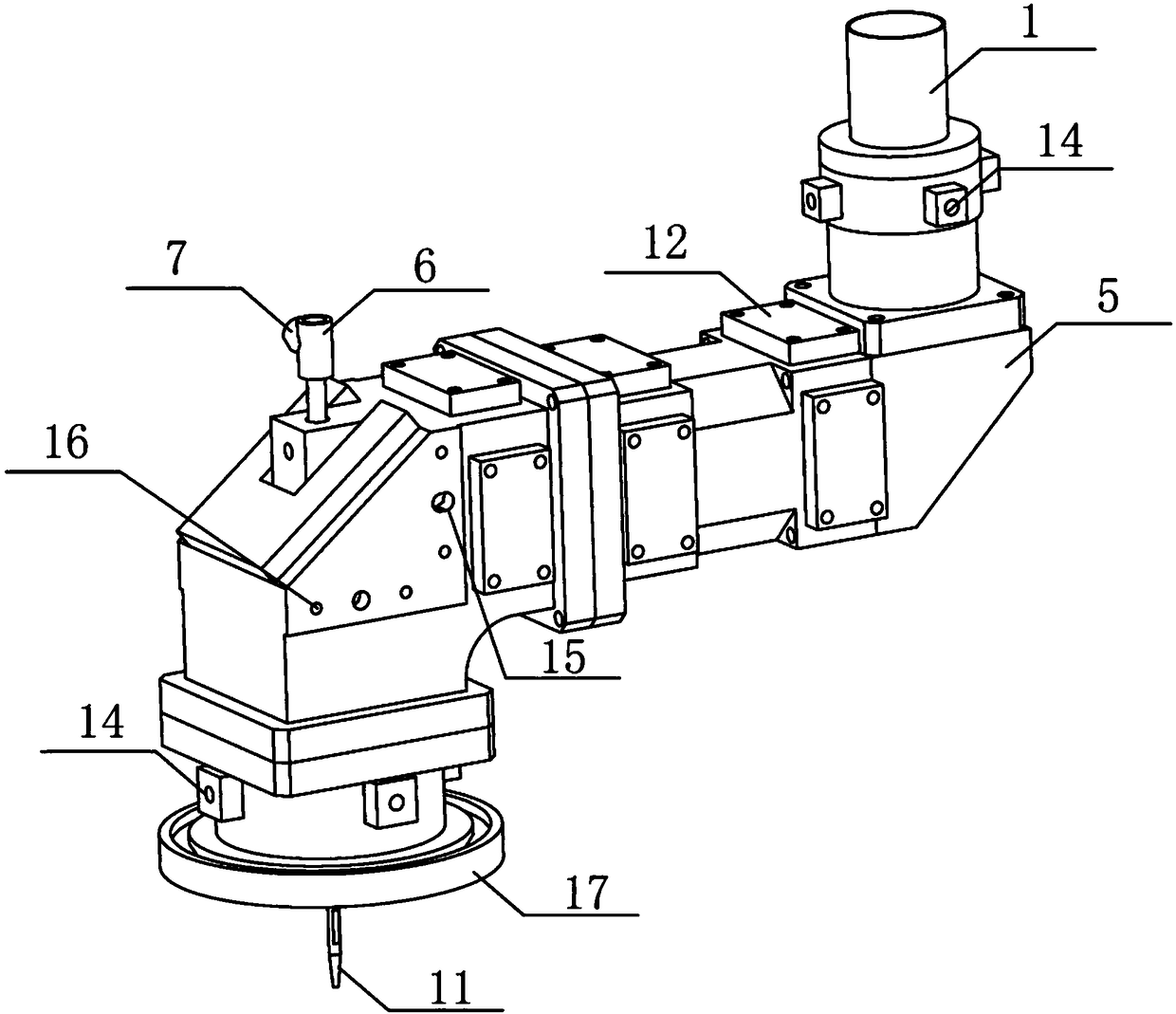
The invention provides a coaxial wire-feeding cladding head for laser metal printing. The coaxial wire-feeding cladding head for laser metal printing comprises a laser device connector, an annular light beam generation device used for converting a solid laser beam to an annular hollow light beam, a wire-feeding pipe, a focusing mirror and a sealed box body, wherein mutually-communicating transmission channel and output channel are formed in the sealed box body, the transmission channel and the output channel are not located on the same axis, a reflecting mirror is arranged at the junction of the transmission channel and the output channel, the reflecting mirror leads the annular hollow light beam into the output channel, and the focusing mirror is arranged in the output channel; and the wire-feeding pipe is arranged in the output channel along a straight line, and coaxial with the annular hollow light beam. The coaxial wire-feeding cladding head for laser metal printing has the following beneficial effects: a metal wire is transmitted to a cladding position from a position coaxial with the laser beam, so that the coaxiality of the metal wire and the annular laser beam is improved;and the convergence angle of the laser beam during re-focusing is reduced, and the stability of the metal wire in a forming process is improved.

Description

technical field [0001] The invention relates to the field of laser metal printing, in particular to a coaxial wire feeding welding head for laser metal printing. Background technique [0002] With the continuous improvement of requirements and demand for large-scale high-performance components in aerospace, nuclear industry and other fields, metal additive manufacturing that takes into account precise forming and high-performance forming has attracted widespread attention at home and abroad. Laser wire-fed metal printing has the advantages of high material utilization, high forming efficiency, high mechanical properties and environmental friendliness, and has great potential application value in the manufacture and repair of high-performance parts. In recent years, research on laser wire-fed metal printing has increased significantly, and remarkable results have been achieved. However, the current research on laser wire-fed metal printing still focuses on the influence of f...

Claims


Application Information

Patent Timeline
Patent Type & Authority Applications(China)
IPC IPC(8): B23K26/342B23K26/064B23K26/70B23K26/14
CPCB23K26/064B23K26/0643B23K26/14B23K26/342B23K26/702B23K26/703
Inventor 周伟民徐栋闵国全司君平黄萍刘宏业王涵
Owner SHANGHAI IND TECH INST
Learn More