
Micropore detecting device and rotating detecting device

A detection device and a technology of rotation detection, applied in the direction of mechanical diameter measurement, sorting, etc., can solve problems such as difficult operation, easy bending of flexible inspection tools, and detection deviations, etc., to achieve accurate detection data, high detection efficiency, and solve the problems of measurement The effect of needle bending

Active Publication Date: 2015-03-25
深圳市特思路精密科技有限公司
View PDF11 Cites 4 Cited by
  • Summary
  • Abstract
  • Description
  • Claims
  • Application Information

AI Technical Summary

Problems solved by technology

[0003] One of the purposes of the present invention is to propose a micropore detection device to solve the technical problems that the flexible stylus is easy to bend / bend during the detection process, which leads to detection deviation and low detection efficiency
When performing precision micro-hole detection on the inner hole of superhard material workpieces such as ceramic ferrules, needle gauges are generally used for manual penetration detection. It is extremely difficult, which leads to low detection efficiency and high cost of needle gauges. In order to reduce costs, ordinary steel wires can be used, but ordinary steel wires are flexible inspection tools (probing needles), and manual inspection is almost impossible to operate, because flexible inspection tools are extremely easy to bend Due to its characteristics, it cannot be used in automatic detection equipment

Method used


Image

  • Micropore detecting device and rotating detecting device
  • Micropore detecting device and rotating detecting device
  • Micropore detecting device and rotating detecting device

Examples


Embodiment Construction

[0019] The present invention will be further described below in conjunction with the accompanying drawings and specific embodiments.

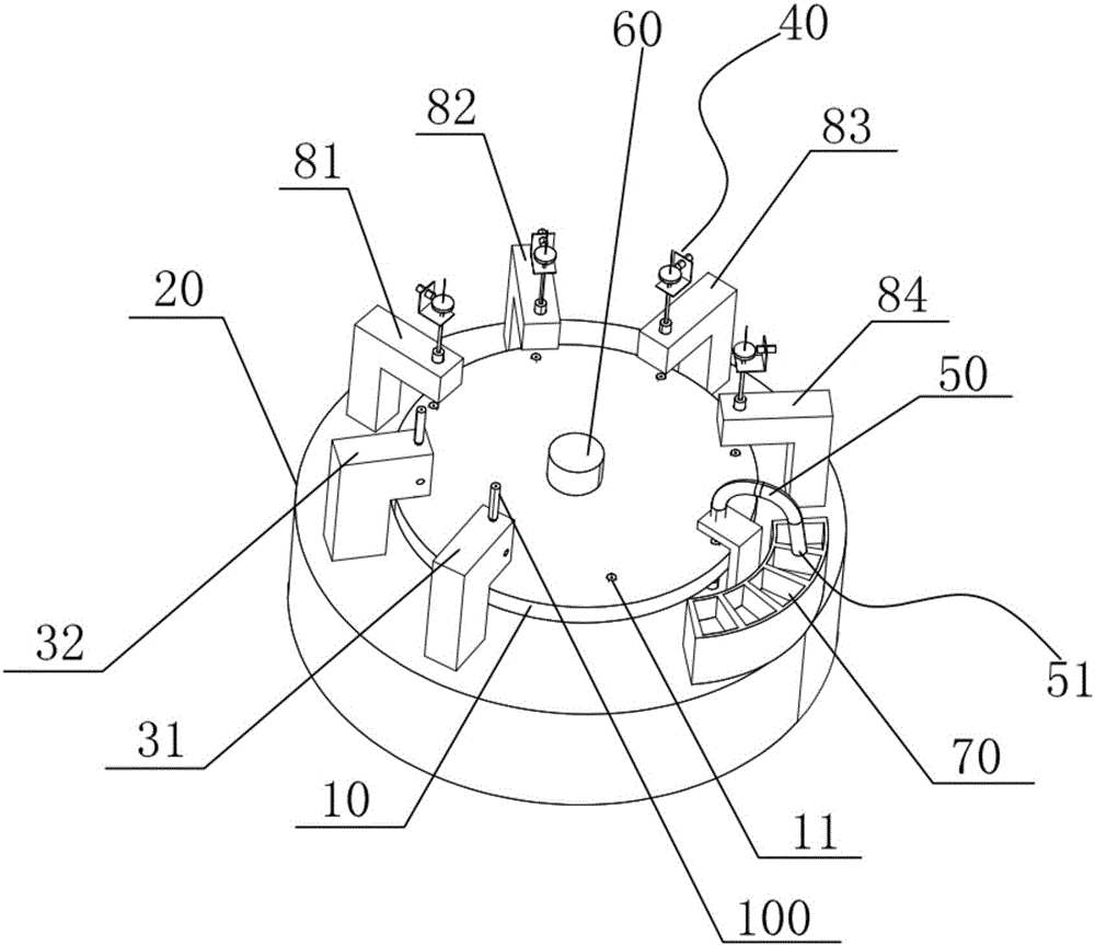
[0020] A specific embodiment of the present invention provides a rotation detection system, which can be used for automatic detection of precision micro-holes (referred to as through-holes) of superhard material workpieces, such as detection of inner holes of ceramic ferrules. Such as figure 1 As shown, the rotation detection system includes a rotary table 10, a support table 20, a feeder, a micropore detection device 40, a discharger 50 and a control system.

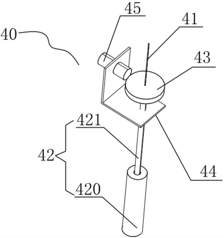
[0021] Such as figure 1 and figure 2 As shown, the microhole detection device 40 includes a stylus 41, a stylus protection mechanism 42, a detection force providing module 43, a movable bracket 44, and a sensing module 45. The stylus protection mechanism 42 includes a movable nested fixed mechanism 420 and sliding mechanism 421, the probe 41 passes through the sliding mechanism 421 a...


PUM


Abstract

The invention discloses a micropore detecting device and a rotating detecting device. The micropore detecting device comprises detecting needles, detecting needle protection mechanisms, weights, movable supports and optical fibers. Each detecting needle protection mechanism comprises a fixed sleeve and a sliding sleeve. The detecting needles penetrate through the sliding sleeves and the fixed sleeves. The movable supports drive the sliding sleeves to move up and down. The weights are fixed to the detecting needles and are pressed on the sliding sleeves, the weights can move up and down along with the sliding sleeves, and the detecting needles can move downwards through the weights. When the movable supports drive the sliding sleeves to move downwards in the fixed sleeves, the detecting needles located in the fixed sleeves move downwards to penetrate through holes of workpieces to be detected. When the movable supports move upwards, the sliding sleeves move upwards in the fixed sleeves and eject the weights upwards so that the detecting needles can be drawn out of the workpieces to be detected. The optical fibers are fixed to the movable supports and used for inducting whether the detecting needles move upwards or not, and therefore whether the detecting needles penetrate through the inner holes of the workpieces to be detected or not can be judged. The rotating detecting system comprises the micropore detecting device used for detecting the inner holes of the workpieces.

Description

technical field [0001] The invention relates to the technical field of microhole detection, in particular to a microhole detection device and a rotation detection system for detecting precision micropores of superhard material devices (such as inner holes of ceramic ferrules). Background technique [0002] Precision micro-holes of ceramic ferrules or other superhard material devices (for example, the inner hole of ceramic ferrules is φ0.125 +0.001mm ) is generally detected manually with a needle gauge (a checking tool). Needle gauges are divided into flexible and rigid. Because the detection aperture is very small, the needle gauges are very thin, and: rigid needle gauges are brittle and easy to break during testing, while flexible needle gauges are easy to bend and bend during testing. Therefore, the current detection method is inefficient, labor-intensive, and detection cost is high; it is also because the needle gauge is easily broken or bent or bent during the detection...

Claims


Application Information

Patent Timeline
Patent Type & Authority Applications(China)
IPC IPC(8): G01B5/12B07C5/06
Inventor 肖湘杰杨荣海吴涛
Owner 深圳市特思路精密科技有限公司
Learn More