
Manufacturing method of BPS-array substrate and BPS-array substrate

A technology for array substrates and manufacturing methods, which is applied to the manufacture of BPS-type array substrates, and in the field of BPS-type array substrates, can solve the problems of large amount of BPS materials, high technical difficulty, and high price, and achieve reduced consumption, simple manufacturing methods, and low cost. The effect of production costs

Inactive Publication Date: 2018-09-14
TCL CHINA STAR OPTOELECTRONICS TECH CO LTD
View PDF7 Cites 18 Cited by
  • Summary
  • Abstract
  • Description
  • Claims
  • Application Information

AI Technical Summary

Problems solved by technology

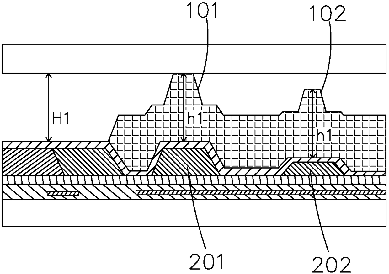
[0005] But at present, the technology of BPS material is relatively difficult, and it has not yet been mass-produced, and the price is expensive. In the existing BPS-type product structure, such as figure 1 As shown, under the main spacer 101 and the auxiliary spacer 102, a single-layer first color resist 201 and a second color resist 202 are used as a spacer carrier, and the space between the main spacer 101 and the auxiliary spacer 102 is The height difference is formed by the thickness difference between the first color resistance 201 and the second color resistance 202. The thickness h1 of the main spacer 101 and the auxiliary spacer 102 is similar to the cell thickness (Cellgap) H1 of the liquid crystal panel. The main spacer Object 101 and auxiliary spacer 102 consume a large amount of BPS material, and the cost is relatively high

Method used


Image

  • Manufacturing method of BPS-array substrate and BPS-array substrate
  • Manufacturing method of BPS-array substrate and BPS-array substrate
  • Manufacturing method of BPS-array substrate and BPS-array substrate

Examples


Embodiment Construction

[0044] In order to further illustrate the technical means adopted by the present invention and its effects, the following describes in detail in conjunction with preferred embodiments of the present invention and accompanying drawings.

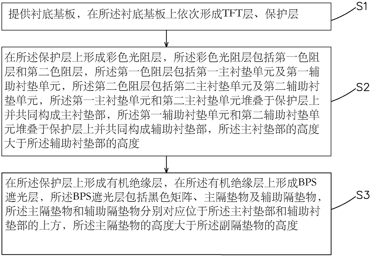
[0045] see figure 2 , the present invention firstly provides a method for manufacturing a BPS type array substrate, comprising the following steps:

[0046] Step S1, such as image 3 As shown, a base substrate 10 is provided, a TFT layer 20 is formed on the base substrate 10 , and a protective layer 30 covering the TFT layer 20 is formed on the base substrate 10 .

[0047] Specifically, in the step 1, the TFT layer 20 includes a scan line 21 and a data line 22 vertically crossing the scan line 21 and insulated.

[0048] Step S2, such as Figure 4 and Figure 6 As shown, a color photoresist layer 40 is formed on the protection layer 30, and the color photoresist layer 40 includes a first color-resist layer 41, a second color-resist layer 4...


PUM


Abstract

The invention provides a manufacturing method of a BPS-array substrate and the BPS-array substrate, wherein the manufacturing method of the BPS-array substrate is that: a double-layer chromatic resistance structure formed by a first chromatic resistance layer and a second chromatic resistance layer is used for respectively padding the main gasket part and the auxiliary gasket part of a main spacerand an auxiliary spacer, and then the main gasket part and the auxiliary gasket part are raised obviously; the thickness of the main spacer and the auxiliary spacer is reduced, thereby reducing the amount of BPS material used for forming the main spacer and the auxiliary spacer and reducing the production cost; the height difference between the main spacer and the auxiliary spacer can be realizedby reducing the thickness of the first chromatic resistance layer below the auxiliary gasket part through the semi-exposure technology, and the manufacturing method is simple.

Description

technical field [0001] The invention relates to the field of display technology, in particular to a method for manufacturing a BPS array substrate and the BPS array substrate. Background technique [0002] Liquid crystal display (Liquid Crystal Display, LCD) is currently the most widely used display product in the market. Its production process technology is very mature, the product yield rate is high, the production cost is relatively low, and the market acceptance is high. Most of the liquid crystal displays currently on the market are backlight liquid crystal display devices, which include a liquid crystal display panel and a backlight module. Generally, a liquid crystal display panel is composed of a color filter (Color Filter, CF) substrate, an array (Array) substrate, a liquid crystal sandwiched between the color filter substrate and the array substrate, and a sealant (Sealant). A color filter layer for colored light is formed through a color resist unit (R / G / B), a bl...

Claims


Application Information

Patent Timeline
Patent Type & Authority Applications(China)
IPC IPC(8): G02F1/1335G02F1/1339G02F1/1362
CPCG02F1/133512G02F1/133514G02F1/133516G02F1/13394G02F1/136209G02F1/1339G02F1/13396G02F1/13398H01L27/1248G02F1/1368G02F1/136222H01L27/1244H01L27/1259
Inventor 邓竹明
Owner TCL CHINA STAR OPTOELECTRONICS TECH CO LTD
Learn More