
Three-dimensional coordinate reference field indoor space measuring, positioning and scanning light face calibration method

A three-dimensional coordinate, indoor space technology, applied in the direction of measuring devices, instruments, etc., can solve the problems of system error, affecting the system measurement accuracy, affecting the coordinate measurement accuracy of multi-transmitting station networking, etc., to achieve the effect of improving the measurement accuracy

Active Publication Date: 2018-09-14
TIANJIN UNIV
View PDF4 Cites 6 Cited by
  • Summary
  • Abstract
  • Description
  • Claims
  • Application Information

AI Technical Summary

Problems solved by technology

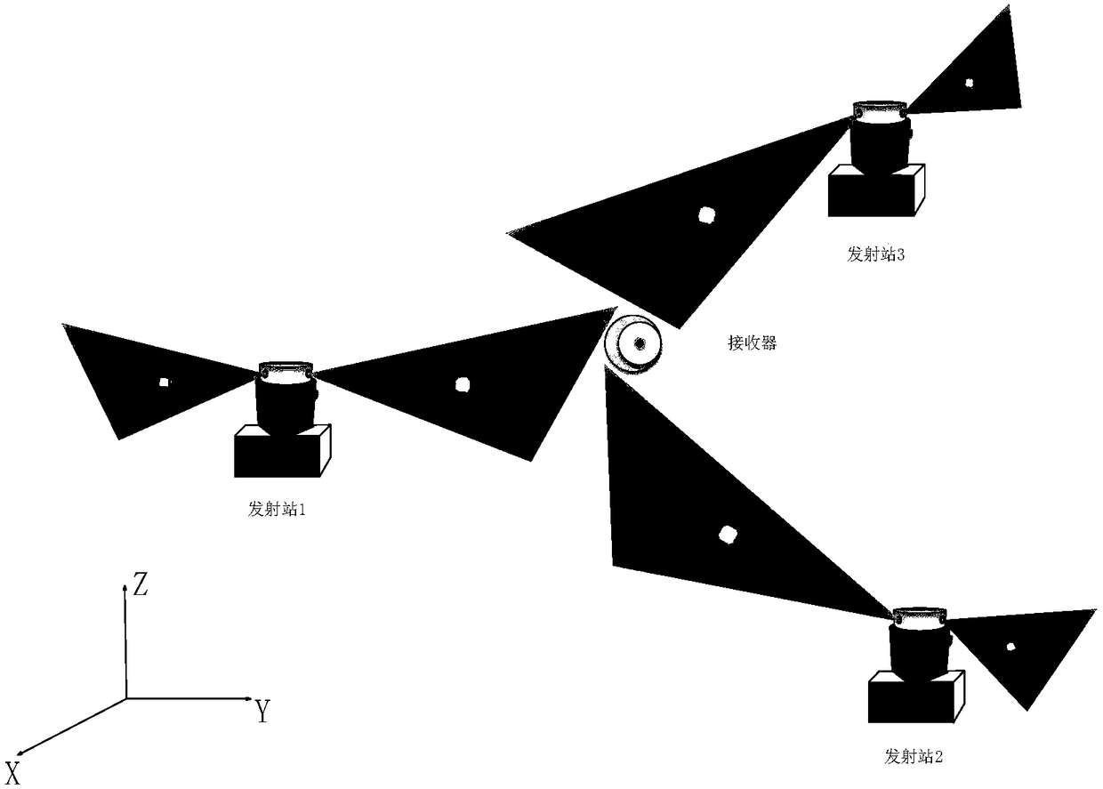
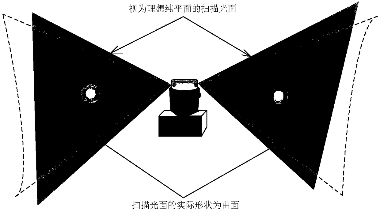
Since the wMPS positioning system uses the intersection of spatial angles under the constraints of the scanning optical surface for three-dimensional coordinate measurement, the degree of fit between the model of the scanning optical surface and the actual shape of the scanning optical surface directly affects the angle measurement performance of a single transmitting station, thereby affecting the entire system measurement accuracy
At this stage, using the ideal plane that deviates from the actual situation as the model of the scanning light surface will cause a certain amount of systematic error in the measurement model of a single transmitting station, thus affecting the coordinate measurement accuracy in the network of multiple transmitting stations

Method used


Image

  • Three-dimensional coordinate reference field indoor space measuring, positioning and scanning light face calibration method
  • Three-dimensional coordinate reference field indoor space measuring, positioning and scanning light face calibration method
  • Three-dimensional coordinate reference field indoor space measuring, positioning and scanning light face calibration method

Examples


Embodiment Construction

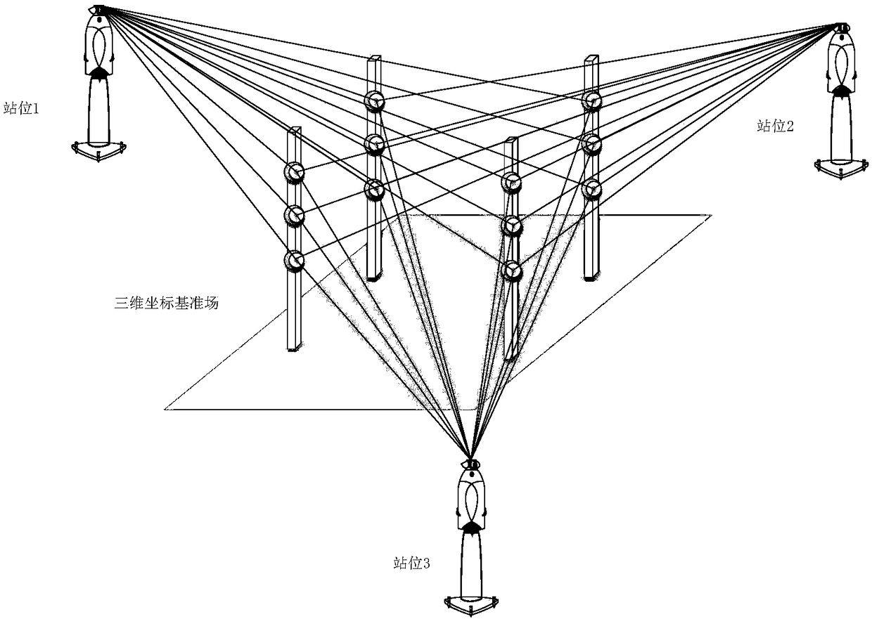
[0048] In view of the actual situation of wMPS, in order to obtain the structural parameters of the scanning optical surface that fit its actual shape, the present invention makes full use of the high precision of laser tracker interferometric distance measurement, and provides a method for calibrating the scanning optical surface of wMPS based on the three-dimensional coordinate reference field to calibrate the scanning surface. After the control points are laid out, the laser tracker is used to measure the error characteristics, the redundant length measurement constraints are established, and the three-dimensional coordinate reference field is constructed by using the method of weighted optimization of the angle measurement error, which is used as the reference for the calibration of the geometric model parameters of the WMPS scanning smooth surface. The method is to establish the actual and exact geometric shape of the scanning surface, and improve the measurement performan...


PUM


Abstract

The invention belongs to large-size measuring technology, aims to acquire scanning light face structure parameters fitted with its actual shape and can improve measuring accuracy of a wMPS system. A three-dimensional coordinate reference field indoor space measuring, positioning and scanning light face calibration method includes: using a laser tracker to measure global control points under multiple stations, and cooperating with a weighting algorithm for optimizing measuring angle errors to acquire a three-dimensional coordinate reference field; taking coordinate field reference as referencefor wMPS scanning light face calibration of an indoor space measuring and positioning system; arranging an emitting station, and measuring and recording moment of each scanning light source when passing each control point; taking a quadric surface as a typical model with scanning light face more fitted with actual shape, establishing a constraint equation through coordinates of the control pointsin reference field space, combining with other constraints, using a least square method to resolve parameters of the scanning light face, and taking the parameters as intrinsic parameters of a wMPS single emitting station for reconfiguration. The method is mainly applied in large-size measuring occasions.

Description

technical field [0001] The invention belongs to an internal reference calibration method for a large-scale measurement system on an industrial site, in particular to a method for calibrating parameters of a scanning smooth surface model of an indoor space measurement and positioning system based on a three-dimensional coordinate reference field. Background technique [0002] Indoor space measurement and positioning system, typically represented by wMPS (workshop Measurement Positioning system), is a multi-station distributed large-space measurement and positioning system developed based on the principle of spatial angle convergence for the measurement needs of large-scale equipment manufacturing industries. It has a wide range of measurement, It has the advantages of high measurement accuracy and multi-task parallel measurement. The measurement system is mainly composed of four parts: multiple transmitting stations deployed in the measurement space, spherical receivers place...

Claims


Application Information

Patent Timeline
IPC IPC(8): G01C25/00
Inventor 林嘉睿邾继贵任永杰杨凌辉徐鑫
Owner TIANJIN UNIV
Learn More