
Pressure intensity mechanical and automatic adjustment viscous damper

A viscous damper and self-adjusting technology, applied in the field of structural shock absorption, can solve the problems of inability to protect the safety of the cylinder block and sealing system, unpredictable internal force redistribution, large differences in calculation models, etc.

Pending Publication Date: 2018-09-14
NANJING FORESTRY UNIV
View PDF2 Cites 5 Cited by
  • Summary
  • Abstract
  • Description
  • Claims
  • Application Information

AI Technical Summary

Problems solved by technology

Therefore, when relative motion occurs at both ends of the viscous damper, its fluid mechanical properties will change greatly, so that the relevant parameters C and α of the viscous damper will change greatly. The calculation models of viscous dampers are very different. Even through refined analysis, the changes in mechanical parameters before and after the difference may lead to unpredictable redistribution of internal forces, and even cause structural unsafety.
Due to the use of controllers, sensors, and solenoid valves, the possibility of circuit failures is greatly increased, and troubleshooting and maintenance are very inconvenient
In addition, controlling the opening or closing of the damping hole through the solenoid valve cannot reduce the pressure value in the two master cylinders, nor can it protect the safety of the cylinder body and the sealing system.

Method used


Image

  • Pressure intensity mechanical and automatic adjustment viscous damper
  • Pressure intensity mechanical and automatic adjustment viscous damper
  • Pressure intensity mechanical and automatic adjustment viscous damper

Examples


Embodiment Construction

[0015] In order to make the object, technical solution and advantages of the present invention clearer, the present invention will be further described in detail below in conjunction with the accompanying drawings and embodiments.

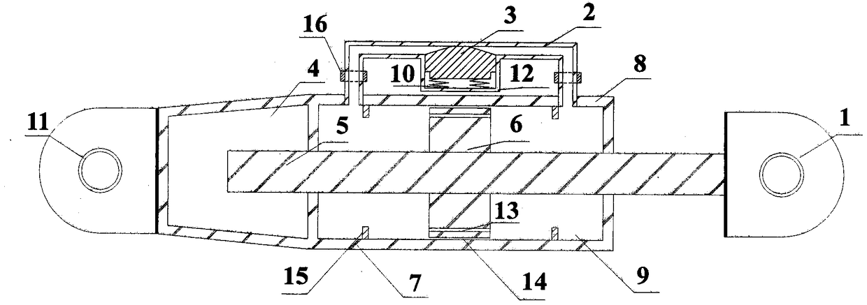
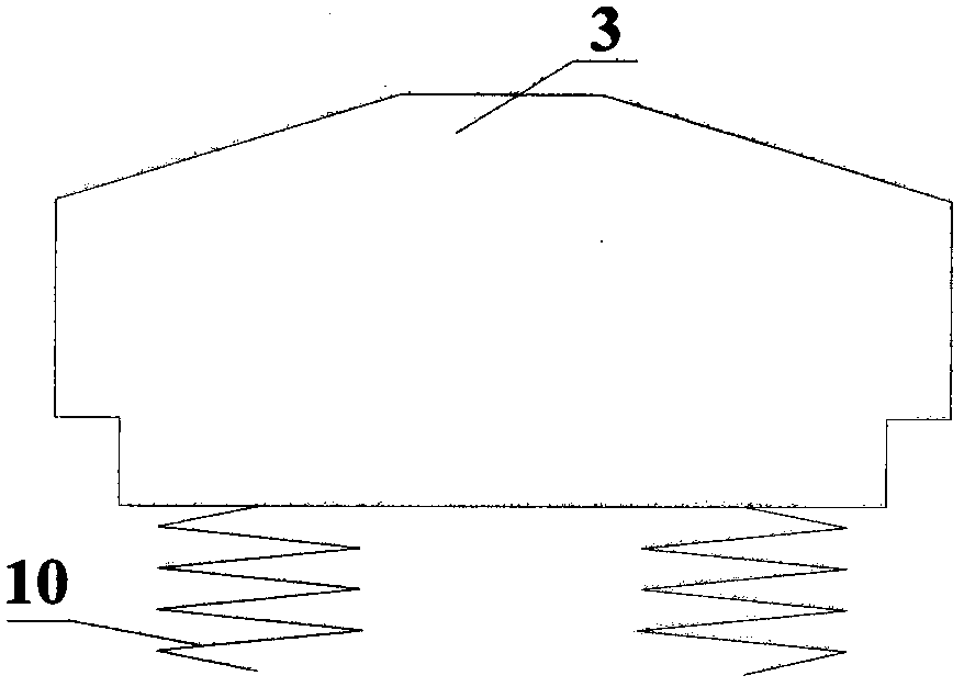
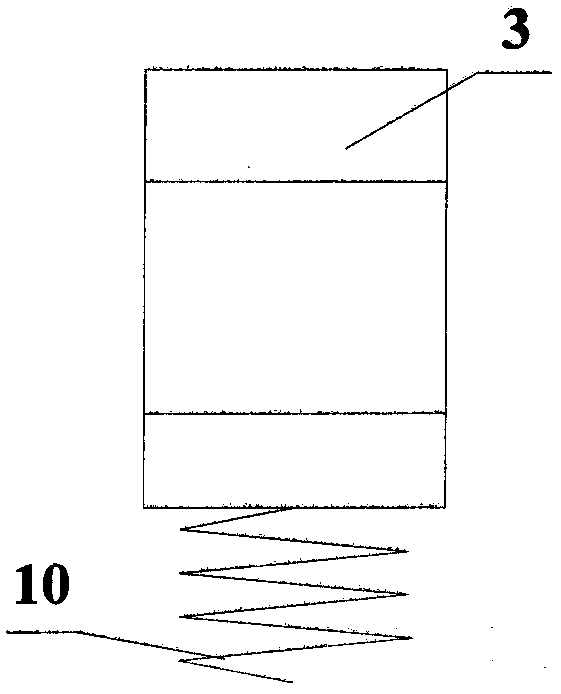
[0016] figure 1 It is a schematic diagram of the overall structure of the self-adjusting pressure type viscous damper according to the present invention. Such as figure 1 As shown, the self-adjusting pressure type viscous damper according to the present invention mainly includes a main cylinder, an auxiliary cylinder 4, a piston 6, a piston rod 5, a liquid pipe 2, a pressure block valve 3, etc., wherein the main cylinder is divided into a left main cylinder Cylinder 7 and right master cylinder 8, left master cylinder 7 and right master cylinder 8 are filled with identical damping medium 9. The piston 6 is arranged between the left master cylinder 7 and the right master cylinder 8 and can move back and forth along its axial direction, thereby dr...


PUM


Abstract

The invention discloses a pressure intensity mechanical and automatic adjustment viscous damper and belongs to the technical field of structural vibration reduction. A damping medium is ejected through damping holes formed in a piston to flow to generate damping force, so that the vibration amplitude is rapidly reduced and the input vibration energy is consumed. A liquid through tube is a round tube; the lower portions of the two ends of the liquid through tube are welded to a left main cylinder and a right main cylinder correspondingly; a pressure block valve is disposed in the middle of theliquid through tube; a spring is connected with the pressure block valve, and a prepressure is set; the damping medium of the left main cylinder and the right main cylinder is blocked by the pressureblock valve; and when the force, generated in the liquid through tube, by the pressure intensity difference of the damping medium of the liquid through tube is larger than the prepressure of the spring, the liquid through tube is in a connected state. The pressure intensity mechanical and automatic adjustment viscous damper is simple in structure, the pressure intensity is adjusted through a mechanical device, all parts and accessories can be pre-fabricated and machined in a factory, the damper is economical and reasonable, the stability of hysteretic curve can be guaranteed, the vibration-reducing protection effect is better, the security coefficient is higher, the structural durability is high, and the damper can be used for a long time.

Description

technical field [0001] The invention relates to the technical field of structural damping, in particular to a mechanically self-adjusting pressure viscous damper. Background technique [0002] The viscous damper generates damping and dissipates vibration energy through the flow of the damping medium in the damping hole. It has the advantages of low maintenance cost, etc. It has a wide application prospect in the anti-seismic and wind control of civil engineering structures, and it is widely used in the anti-seismic reinforcement of existing buildings or post-earthquake repair projects and new projects, and has achieved good results. . The basic formula of the viscous damper is F=CV α , where F represents the damping force, C is the damping coefficient, V represents the speed of the piston movement, and α is the speed index. It can be seen from the formula that the viscous damper belongs to the velocity type damper, and its velocity index directly affects the energy dissip...

Claims


Application Information

Patent Timeline
IPC IPC(8): F16F9/19F16F9/512
CPCF16F9/19F16F9/5123
Inventor 苏毅韩煦智张冲石雅平周爱萍黄东升
Owner NANJING FORESTRY UNIV
Learn More