Gas-liquid isolating tank based on flexible transmission, and application thereof in gas-liquid linkage actuator
A gas-liquid isolation and flexible transmission technology, which is applied in the direction of engine components, accumulator devices, fluid pressure actuation devices, etc., can solve problems such as impact, poor environmental performance, hydraulic oil overflow, etc., to reduce air pollution and reduce Effects of Hydraulic Oil Contamination
- Summary
- Abstract
- Description
- Claims
- Application Information
AI Technical Summary
Problems solved by technology
Method used
Image
Examples
Embodiment 1
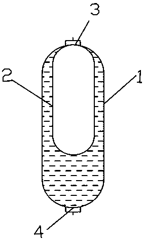
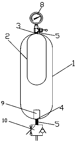
[0048] Such as figure 1 with figure 2 As shown, a gas-liquid isolation tank based on flexible transmission includes a tank body 1, an isolation bladder 2, an air inlet and outlet 3 arranged at the top of the tank 1, and a liquid inlet and outlet 4 arranged at the bottom of the tank 1. The opening of the isolation bladder 2 is sealed and installed on the air inlet and outlet 3, and the isolation bladder 2 isolates the inner cavity of the tank body 1 into a gas cavity and a liquid cavity. The inside is a gas cavity and the outside is a liquid cavity.
Embodiment 2
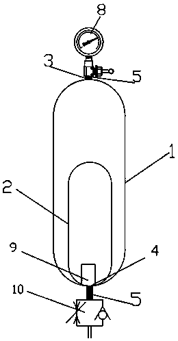
[0050] Such as image 3 As shown, a gas-liquid isolation tank based on flexible transmission includes a tank body 1, an isolation bladder 2, an air inlet and outlet 3 arranged at the top of the tank 1, and a liquid inlet and outlet 4 arranged at the bottom of the tank 1. The opening of the isolation bladder 2 is sealed and installed on the liquid inlet and outlet 4, and the isolation bladder 2 isolates the inner cavity of the tank body 1 into a gas cavity and a liquid cavity. The inside is a liquid cavity and the outside is a gas cavity. The difference between the second embodiment and the first embodiment is that the installation position of the isolation airbag 2 is different, and the settings of the other components are the same, and the achieved effect and function are also the same.
[0051] As a preferred embodiment, such as Image 6 As shown, both the air inlet and outlet 3 and the liquid inlet and outlet 4 are provided with a connecting joint 5, and a plurality of ribs 6 a...
Embodiment 3
[0053] Such as figure 2 with image 3 As shown, the upper end of the tank 1 is also provided with a pressure gauge 8 for real-time monitoring of its internal pressure and an interface connected to a pneumatic control system. The liquid inlet and outlet 4 in the tank 1 is provided with a liquid filter device 9 for filtering impurities of liquid such as hydraulic oil. The external pipe of the liquid inlet and outlet 4 is provided with a pressure regulating valve 10 for adjusting the liquid (hydraulic oil) Flow rate, thereby controlling the speed of pressure release, ensuring that the elastic motion process and motion speed are precisely controllable. The connection joint 5 is also provided with a shut-off valve 20 for closing or opening the gas-liquid isolation tank at any time.
[0054] Generally speaking, the pressure vessel tank is the main energy storage device and the main body of compressed gas storage; the bottom hydraulic oil is not only the airtight and insulating medium ...
PUM
 Abstract
Description
Claims
Application Information
 - R&D
- Intellectual Property
- Life Sciences
- Materials
- Tech Scout
- Unparalleled Data Quality
- Higher Quality Content
- 60% Fewer Hallucinations
Browse by: Latest US Patents, China's latest patents, Technical Efficacy Thesaurus, Application Domain, Technology Topic, Popular Technical Reports.
© 2025 PatSnap. All rights reserved.Legal|Privacy policy|Modern Slavery Act Transparency Statement|Sitemap|About US| Contact US: help@patsnap.com


