
Speed reducer, driving wheel, and carriage

A technology for transporting trolleys and driving wheels, which is applied in the fields of reducers, driving wheels and transporting trolleys

Active Publication Date: 2018-09-14
NABLESCO CORP
View PDF16 Cites 0 Cited by
  • Summary
  • Abstract
  • Description
  • Claims
  • Application Information

AI Technical Summary

Problems solved by technology

As a result, the output of the reducer is limited by the outer diameter of the wheel the reducer is mounted on

Method used


Image

  • Speed reducer, driving wheel, and carriage
  • Speed reducer, driving wheel, and carriage
  • Speed reducer, driving wheel, and carriage

Examples


Embodiment Construction

[0036] Hereinafter, an embodiment of the present invention will be described with reference to the drawings. Among them, the drawings attached to this specification are simplified, and the drawings may include, for example, the dimensions of each element, the dimensional ratio between each element, and the specific shape of each element that are different from the actual parts. However, those skilled in the art can fully understand the embodiments described below and other embodiments of the present invention from such simplified drawings.

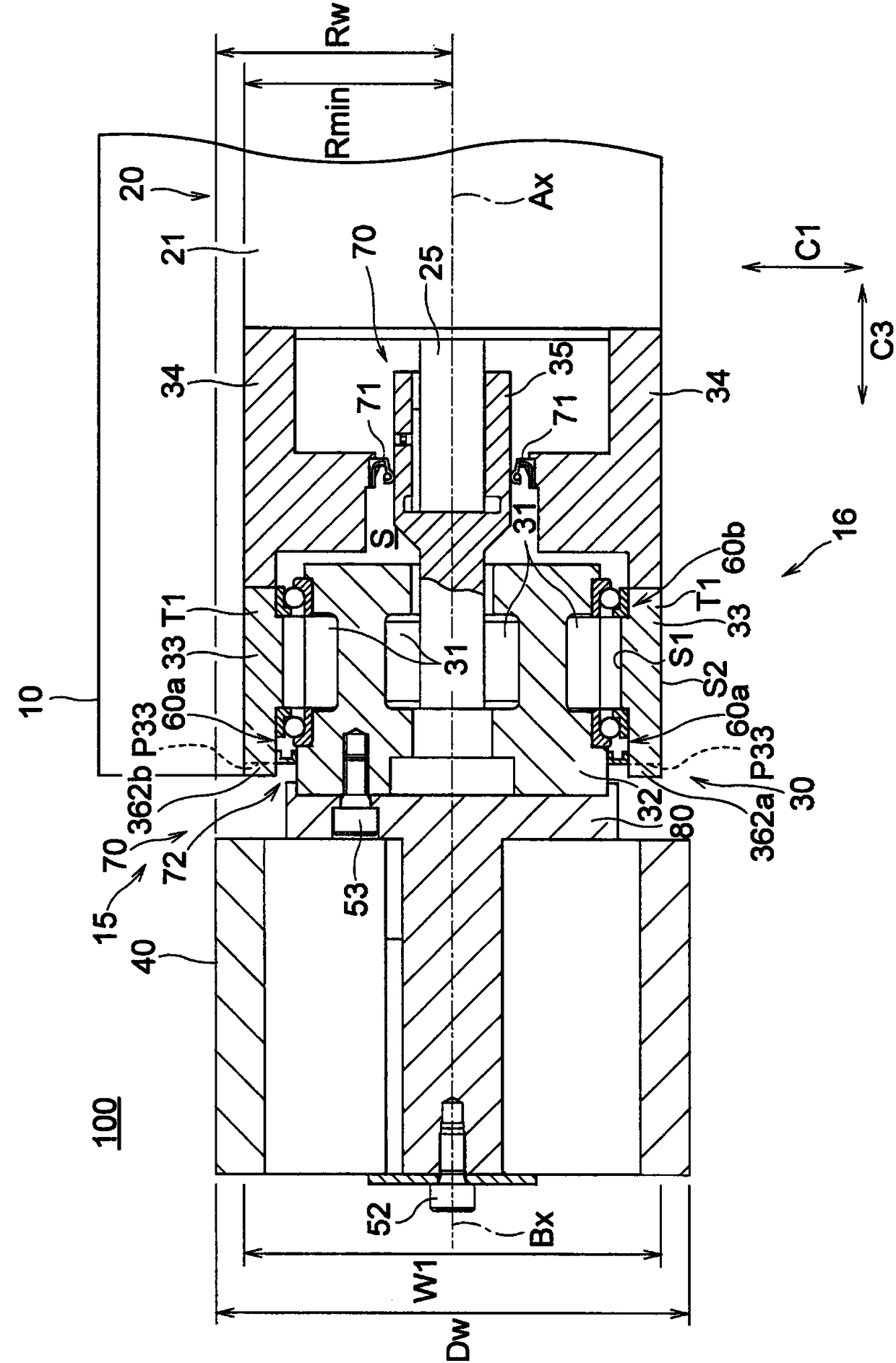
[0037] figure 1 It is a figure which looked at the drive wheel attached to the conveyance trolley which concerns on one Embodiment of this invention from the direction parallel to the rotation axis. and, figure 2 and image 3 respectively figure 1 The II-II line sectional view and the III-III line sectional view of the drive wheel shown.

[0038] Such as figure 1 As shown, the transfer trolley 100 includes a vehicle body 10 and driv...


PUM


Abstract

The invention provides a speed reducer, a driving wheel, and a carriage. The speed reducer (30) which decelerates rotation input from a motor (20) and outputs decelerated rotation to a wheel (40) includes: a case (33) fixed to a carriage body (10); an input portion (35) for receiving the rotation input from the motor (20); an output portion (32) for outputting the rotation to the wheel (40); and aspeed reducing mechanism (31) at least partially housed in the case (33) and configured to decelerate rotation of the input portion (35) and transmit the decelerated rotation to the output portion (32). The maximum outer radius (Rmax) of the case (33) from the rotation axis (Ax) of the output portion (32) is larger than the radius (Rw) of the wheel (40), and the minimum outer radius (Rmin) of thecase (33) from the rotation axis (Ax) of the output portion (32) is smaller than the radius (Rw) of the wheel (40).

Description

technical field [0001] The invention relates to a speed reducer, a driving wheel including the speed reducer, and a transport trolley. Background technique [0002] Transport trolleys driven by motors are used in various fields. As we all know, there are not only manned transport trolleys, but also unmanned RGV (Rail Guided Vehicle) and AGV (Automatic Guided Vehicle). Leading vehicles) and other handling trolleys. In these transport vehicles, the power output from the motor is transmitted to the wheels via the speed reducer, and these transport vehicles travel. The speed reducer is used to decelerate the power output from the motor and output the power with increased torque. [0003] In addition, generally, the larger the output of the reducer, the larger the reducer tends to be. On the other hand, the size seen when the speed reducer is viewed from a direction parallel to the rotation axis of the speed reducer is limited to be smaller than the outer diameter of the wheel...

Claims


Application Information

Patent Timeline
Patent Type & Authority Applications(China)
IPC IPC(8): B60K17/04
CPCB60K17/043B60Y2200/62B60K7/0007F16H2057/02034F16H57/025B60K2007/0092F16H1/28F16H57/03B60K17/046B60K1/00
Inventor 中村江児成瀬隆
Owner NABLESCO CORP
Learn More