Novel pipefitting clamping device for industrial robot

An industrial robot and clamping device technology, applied in the field of robots, can solve the problems of difficult fixing, large limitations, and difficulty in realizing multi-directional engraving, and achieve the effect of ensuring quality control.

Inactive Publication Date: 2018-09-14
邵潘英
View PDF0 Cites 2 Cited by
  • Summary
  • Abstract
  • Description
  • Claims
  • Application Information

AI Technical Summary

Problems solved by technology

[0002] Engraving robots are widely used in industrial production, but traditional engraving robots are difficult to fix when engraving workpieces, which seriously affects the engraving effect. At the same time, traditional engraving robots have large limitations in the engraving process and are difficult to achieve multi-directional Engraving needs

Method used


Image

  • Novel pipefitting clamping device for industrial robot
  • Novel pipefitting clamping device for industrial robot
  • Novel pipefitting clamping device for industrial robot

Examples


Embodiment Construction

[0013] The following will clearly and completely describe the technical solutions in the embodiments of the present invention with reference to the accompanying drawings in the embodiments of the present invention. Obviously, the described embodiments are only some, not all, embodiments of the present invention. Based on the embodiments of the present invention, all other embodiments obtained by persons of ordinary skill in the art without making creative efforts belong to the protection scope of the present invention.

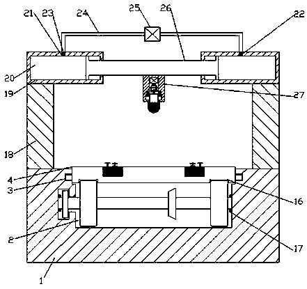
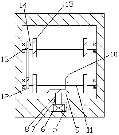
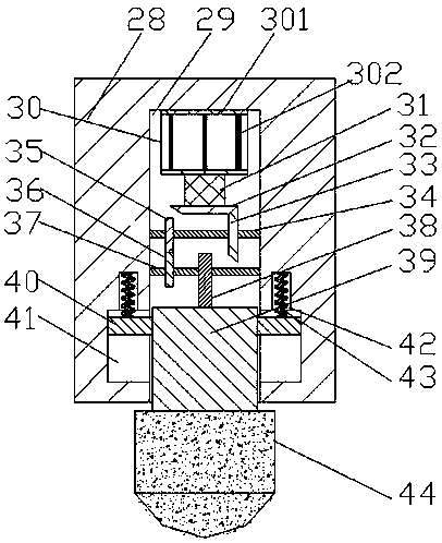
[0014] see Figure 1-4, an embodiment provided by the present invention: a new type of pipe clamping device for industrial robots, including a frame 1, a transition cavity 2 is arranged inside the frame 1, and the upper end wall of the transition cavity 2 The left and right ends are equally provided with a sliding joint groove 3, the sliding joint groove 3 communicates with the adapter cavity 2 and the assembly platform 4, and the assembly platform 4 is connec...


PUM


Abstract

The invention discloses a novel pipefitting clamping device for an industrial robot. The novel pipefitting clamping device comprises a rack, wherein a through connection cavity is formed in the rack;slip grooves are equally formed in the left and right ends of the upper end wall of the through connection cavity; the slip grooves communicate to the through connection cavity and an assembling table; the assembling table is in slip connection to the rack through the slip grooves in a matched manner; a mounting and connecting hole is formed in the front end wall of the through connection cavity;a first electro-rotor is fixedly connected to the front end wall of the mounting and receiving hole; a through connecting hole is formed in the front end wall of the mounting and receiving hole; the through connecting hole communicates to the mounting and receiving hole and the through connection cavity; the first electro-rotor is in power connection to a through connecting shaft A, the front endof which penetrates through the through connecting hole; a fixedly connected cone edge wheel A is arranged at the front end of the through connecting shaft A; and the cone edge wheel A is provided with a cone edge wheel B in matched connection to the cone edge wheel A.

Description

technical field [0001] The invention relates to the technical field of robots, in particular to a novel pipe clamping device for industrial robots. Background technique [0002] Engraving robots are widely used in industrial production, but traditional engraving robots are difficult to fix when engraving workpieces, which seriously affects the engraving effect. At the same time, traditional engraving robots have large limitations in the engraving process and are difficult to achieve multi-directional Engraving needs. Contents of the invention [0003] The object of the present invention is to provide a new type of pipe clamping device for industrial robots to solve the problems raised in the above-mentioned background technology. [0004] In order to achieve the above object, the present invention provides the following technical solutions: a new type of pipe fitting clamping device for industrial robots, including a frame, a transition chamber is arranged inside the fram...

Claims


Application Information

Patent Timeline
Patent Type & Authority Applications(China)
IPC IPC(8): B23K26/362B23K26/70B23K37/053B23K26/08B23K101/06
CPCB23K26/083B23K26/0876B23K26/361B23K26/702B23K37/0533
Inventor 邵潘英
Owner 邵潘英
Why Eureka
Try Eureka