
Bone clamping device

A clamping device and bone technology, applied in the field of medical devices, can solve problems such as large clamping force, bone movement, and adding auxiliary equipment, so as to improve precision and work efficiency, realize clamping and fixation, and increase clamping force Effect

Pending Publication Date: 2018-09-14
苏州尚贤医疗机器人技术股份有限公司
View PDF10 Cites 5 Cited by
  • Summary
  • Abstract
  • Description
  • Claims
  • Application Information

AI Technical Summary

Problems solved by technology

[0003] The disadvantages of the current bone clamping method and simple fixation device are: (1) The material properties of the simple fixation device are not good, and it is not easy to clean and disinfect repeatedly, and the device may be damaged due to excessive clamping force; (2) It is held by hand Bones or simple fixation devices cannot provide a large clamping force, and bone clamping instability is prone to occur during the operation, resulting in a decrease in operating accuracy and injury to the doctor's body parts; (3) Simple fixation devices are not easy to withstand During the osteotomy process, spray physiological saline on the instruments and bones to cool down; (4) The contact area between the clamping working plane of the simple fixing device and the bones is small, and the bones are prone to move or slip during the operation. It will lead to the destruction of the operation path of the osteotomy robot or the doctor's hand-held instrument, thereby affecting the accuracy and effect of the operation; (5) For different types of allograft bones, the simple fixation device cannot simultaneously clamp bones of various sizes and shapes, and requires frequent Replacing tools with other clamping ranges or adding auxiliary equipment increases the cost and complexity of surgical operations; (6) For orthopedic surgery robots or doctors operating on bones, the clamping height of the simple fixation device is insufficient and cannot be performed according to the actual situation. Flexible rotation of the direction of the clamped bone cannot provide enough operating space for orthopedic robots or doctors, which in turn affects the effect and efficiency of surgery

Method used


Image

  • Bone clamping device
  • Bone clamping device
  • Bone clamping device

Examples


Embodiment 1

[0093] Such as image 3 As shown, a bone clamping device, the clamping device is provided with a clamping part, the clamping part 1 includes an auxiliary tightening screw 11, a fixed end clamping plate 12, a moving end clamping plate 13, a fixed end heightening piece 14. The height increasing part 15 of the mobile end, the propulsion threaded rod support seat 16, the propulsion threaded rod 17, the clamping base 18 and the propulsion screw positioning screw 19;

[0094] A number of auxiliary set screws 11 for auxiliary clamping are installed on the fixed end clamping plate 12 and the moving end clamping plate 13 respectively;

[0095] The clamping plate 12 at the fixed end and the clamping plate 13 at the movable end are respectively fixed on the height increasing piece 14 at the fixed end and the heightening piece 15 at the moving end, and the clamping plate 12 at the fixed end and the heightening piece 14 at the fixed end are installed and fixed on one side of the clamping b...

Embodiment 2

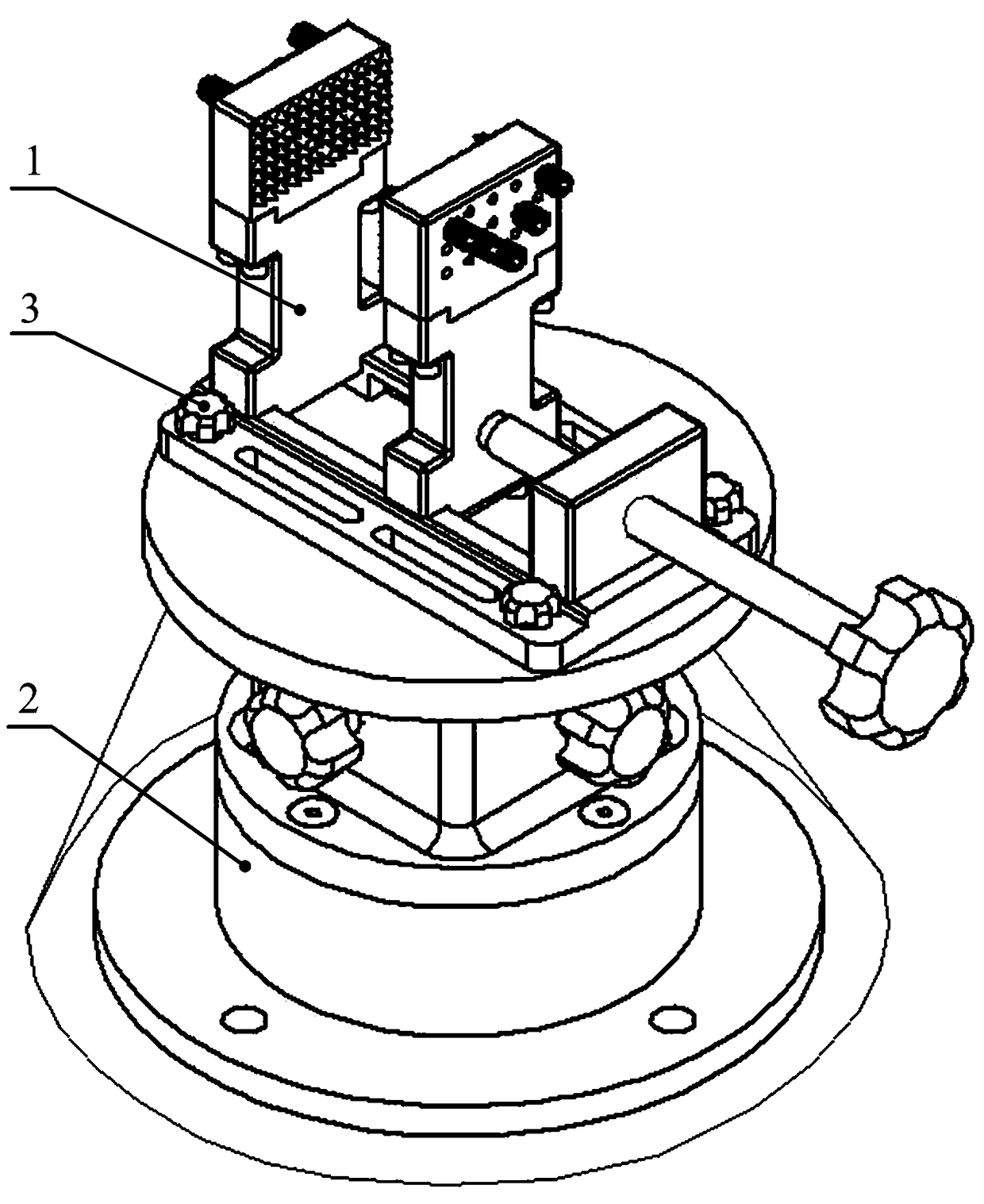
[0110] Such as figure 1 and figure 2 As shown, a bone clamping device includes a clamping part 1 and a rotating table 2, and the rotating table 2 fixes the clamping part 1 through a plum blossom connecting bolt 3;

[0111] Such as image 3 and Figure 4 As shown, the clamping part 1 includes an auxiliary tightening screw 11, a fixed end clamping plate 12, a movable end clamping plate 13, a fixed end heightening piece 14, a moving end heightening piece 15, a push thread rod support seat 16, a push thread Rod 17, clamping base 18 and push screw rod set screw 19;

[0112] A number of auxiliary set screws 11 for auxiliary clamping are installed on the fixed end clamping plate 12 and the moving end clamping plate 13 respectively;

[0113] The clamping plate 12 at the fixed end and the clamping plate 13 at the movable end are respectively fixed on the height increasing piece 14 at the fixed end and the heightening piece 15 at the moving end, and the clamping plate 12 at the fix...


PUM


Abstract

The invention discloses a bone clamping device, and belongs to the field of medical instruments. The device comprises a clamping portion and a rotary working table; the clamping portion is fixed by the rotary working table through a torx connecting bolt; and the bone clamping device can be integrally or separately used according to actual conditions, and is suitable for various application scenarios. The shortcoming that a special bone clamping instrument does not exist in various replacements of traditional allograft bones can be overcome, problems that a traditional auxiliary tool cannot maintain clamping stability and cannot bear spraying cooling of normal saline, the types of clamped bones are limited, a large clamping range cannot be provided, a sufficient operation space cannot be provided, flexible rotary positioning cannot be carried out, and the operation is complicated are solved, surgical bones can be stably clamped, the bone clamping device is suitable for most of types ofbones, a sufficient operation space is provided for robots or doctors in an orthopedics department, the bone clamping device is simple to operate and controllable in power, precision of operation to bones is improved, and the surgery efficiency is improved.

Description

technical field [0001] The invention relates to the technical field of medical instruments, in particular to a bone clamping device for metal materials used in orthopedic surgery. Background technique [0002] The bone clamping device is mainly used in all kinds of allograft bone cutting and replacement operations in orthopedic surgery, and it has a good auxiliary fixation effect on drilling, cutting, grinding and other operations of bones. At present, in orthopedic surgery, there is no better special clamping instrument for fixing the best position of the bone in the auxiliary operation of the allogeneic bone. Doctors can only use the bone in the bone bank for drilling, cutting, grinding and other operations of the allogeneic bone. Hands are directly held on the operating table or clamped on a simple fixing device, and bone drills, bone saws, bone milling cutters and other instruments are used to operate, and the required bones are sterilized after treatment, and finally tr...

Claims


Application Information

Patent Timeline
Patent Type & Authority Applications(China)
IPC IPC(8): A61B90/14
CPCA61B90/14
Inventor 邹运郭征裴延军张云光
Owner 苏州尚贤医疗机器人技术股份有限公司
Learn More