
Multi-functional storage battery charging and discharging device and control method thereof

A charge-discharge device and control method technology, applied to battery circuit devices, circuit devices, output power conversion devices, etc., can solve problems such as low power factor on the grid side, evaporation of battery electrolyte, and small output power factor on the AC side. Achieve the effect of increasing the equivalent switching frequency, realizing balanced power distribution, and reducing the output filter inductance

Active Publication Date: 2018-09-11
XI AN JIAOTONG UNIV
View PDF6 Cites 12 Cited by
  • Summary
  • Abstract
  • Description
  • Claims
  • Application Information

AI Technical Summary

Problems solved by technology

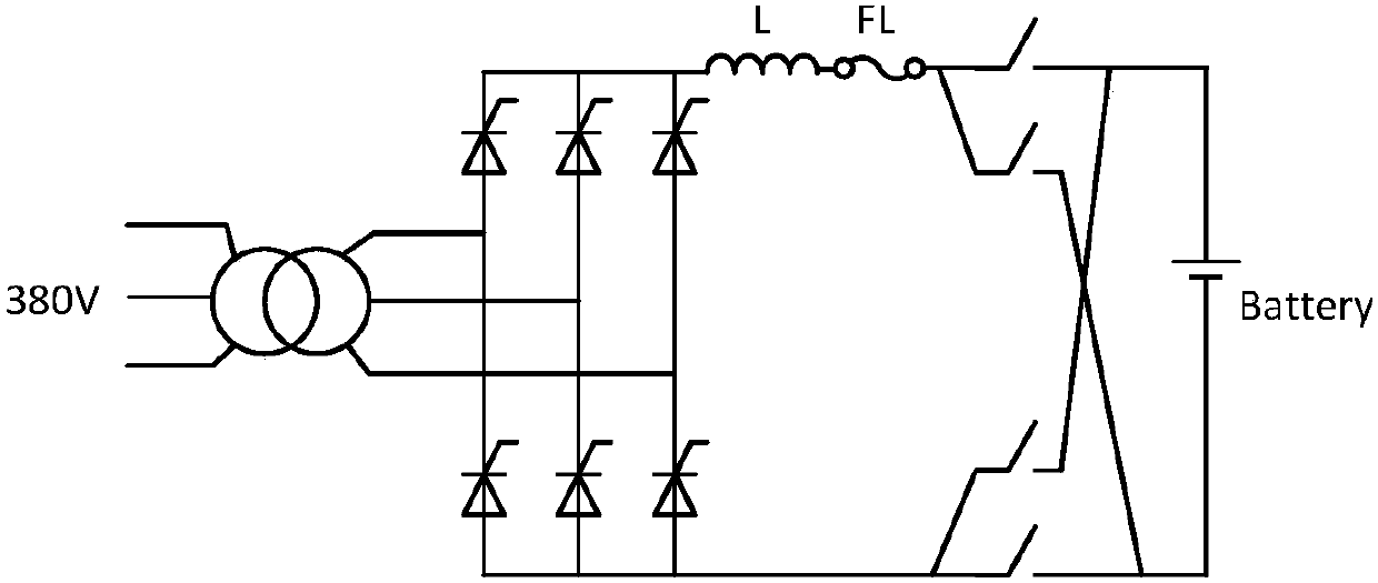
However, in practical applications, the pulsation component of the output current is relatively large, which easily causes the battery electrolyte to heat up and evaporate. In addition, the power factor of the grid side is low, the harmonic pollution is serious, and the failure rate is high.
[0004] For the discharge device, phase-controlled active inverter battery discharge device or resistance discharge device is mostly used, among which: the phase-controlled active discharge device has the disadvantages of large volume and noise, low output power factor of the AC side, and serious pollution to the power grid; Although the resistance discharge device is simple in structure and low in cost, it is difficult to control the discharge current, and the power loss is large, so it is difficult to meet the requirement of constant current discharge of the battery.

Method used


Image

  • Multi-functional storage battery charging and discharging device and control method thereof
  • Multi-functional storage battery charging and discharging device and control method thereof
  • Multi-functional storage battery charging and discharging device and control method thereof

Examples


Embodiment Construction

[0047] The present invention will be further described below in conjunction with the accompanying drawings and specific embodiments.

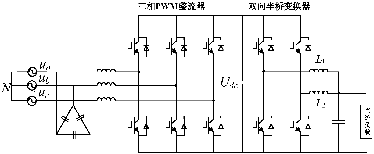
[0048] The present invention adopts two-stage conversion, the front-stage AC / DC unit adopts three-phase PWM rectifier to obtain the DC side voltage, reduces the grid-side input current harmonics, improves the power factor, and reduces energy loss; the rear-stage DC / DC unit adopts interleaved parallel connection The bidirectional half-bridge converter greatly reduces the output filter inductance, thereby reducing the size and weight of the entire device.

[0049] The present invention includes charge and discharge units, such as figure 2 As shown, each charging and discharging unit includes a three-phase PWM rectifier, an interleaved parallel bidirectional half-bridge converter, two output filter inductors and an output filter capacitor, wherein: the three-phase PWM rectifier is a three-phase power switch device containing six The bridge arm r...


PUM


Abstract

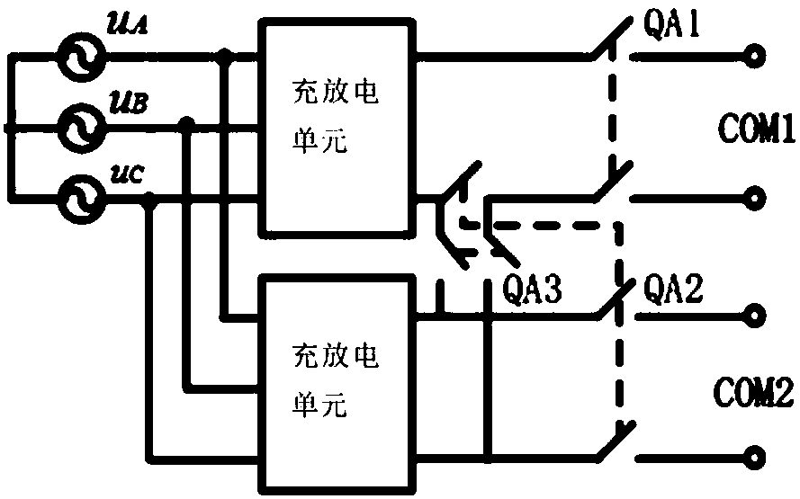
The invention discloses a multi-functional storage battery charging and discharging device and a control method thereof. The device adopts two-stage transformation. A front-stage unit adopts a three-phase PWM rectifier to obtain a DC-side voltage, the grid-side access current harmonics is reduced, the power factor is improved, and the energy loss is reduced; a rear-stage unit uses an interleaved parallel bidirectional half-bridge converter to greatly reduce the output filter inductance. The three-phase PWM rectifier adopts a double closed-loop control strategy of the voltage outer loop and thecurrent inner loop to realize high-precision control of the DC bus voltage and high-power factor control of the grid-side current; when the bidirectional half-bridge converter controls the output voltage, the double closed-loop control strategy of the voltage outer loop and the current inner loop is adopted to use the single loop control of the inner current loop during control of the output current; when a storage battery is charged, the control current is positive, and when the storage battery is discharged, the control current is negative; and when more power is required, the output ends of the two devices are switched to work in series or in parallel through a switch.

Description

technical field [0001] The invention belongs to the technical field of battery charging and discharging, and in particular relates to a multifunctional battery charging and discharging device and a control method thereof. Background technique [0002] As an energy storage device, the battery has the advantages of stable voltage, reliable power supply, and convenient movement. It is widely used in various sectors of the national economy, such as railways, post and telecommunications, ports, and power systems. The charging and discharging technology of the battery is born with the battery, and has a close relationship with the development and application of the battery. The performance of the charging and discharging device directly affects the technical state and service life of the battery, and determines the degree of pollution to the grid during discharge. [0003] At present, the high-power battery charging device commonly used in China is mainly the thyristor rectifier ...

Claims


Application Information

Patent Timeline
IPC IPC(8): H02J7/00H02J7/02H02M7/797H02M7/81
CPCH02J7/022H02J7/0068H02M7/797H02M7/81H02J2207/20H02M1/0067
Inventor 贾要勤潘景宜裴云庆
Owner XI AN JIAOTONG UNIV
Learn More