Method for constructing pursuit barrier for spacecraft by analysis and method for determining capture and escape areas
A spacecraft and structure technology, which is applied in the field of spacecraft pursuit and escape game path planning, can solve the problems of unfavorable pursuit and escape game motion laws, complex countermeasure models, and difficult countermeasures
- Summary
- Abstract
- Description
- Claims
- Application Information
AI Technical Summary
Problems solved by technology
Method used
Image
Examples
Embodiment 1
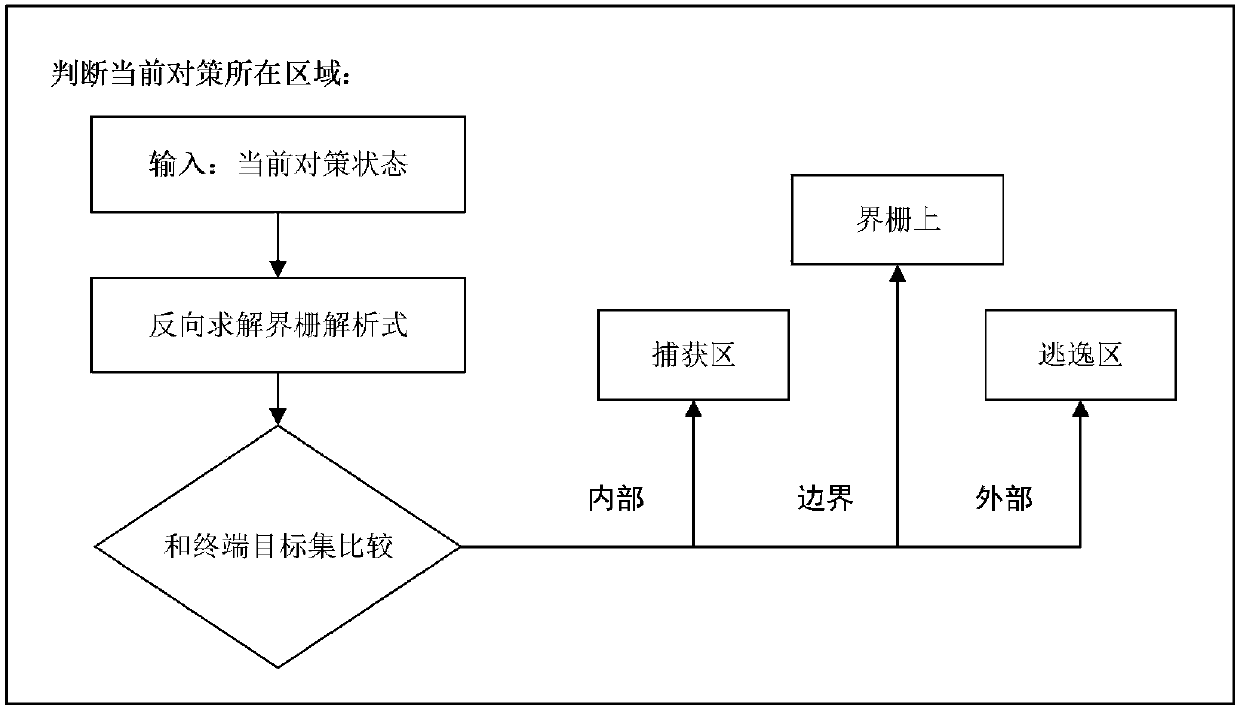
[0099] Such as figure 1 As shown, the steps of a method for analyzing and constructing a boundary barrier for spacecraft chasing and fleeing in this embodiment include:
[0100] S1, using the differential game method to construct the initial model;
[0101] S101, constructing the Hamilton function of the differential game based on the C-W equation,
[0102] 1) Establish the LVLH (Local Vertical Local Horizontal) coordinate system, and construct the motion state equation based on the C-W equation;
[0103] A virtual spacecraft near the two pursued and escaped spacecraft is used as a reference spacecraft to establish a local orbital coordinate system. The origin of the coordinate system is located at the center of mass o of the reference spacecraft, the ox axis is along the radial direction of the reference spacecraft, and the oz axis is along the reference spacecraft The normal direction of the orbital plane of the spacecraft, the y-axis is tangential to the trajectory of the...
Embodiment 2
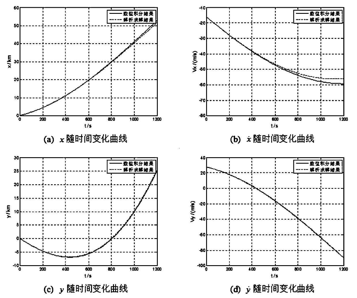
[0161] The steps of this embodiment are basically the same as those of Embodiment 1, and the main difference is that in this embodiment, the azimuth angle of the capture point is no longer a given value, but an independent variable. Therefore, the azimuth angle of different capture points can be obtained by calculation The boundary barrier of the lower differential game at the time τ=1200s.
[0162] Then compare the results of the numerical integration with the results of the analytical solution, see Figure 4 . From the figure, it can be seen that the azimuth Only has a certain impact on the analytical solution accuracy of the position in the y direction of the boundary grid, when or The error is obvious when it is near, but the azimuth angle has little influence on the solution of other boundary grid state quantities.
Embodiment 3
[0164] The steps of this embodiment are basically the same as those of Embodiment 2, the main difference being: in this embodiment, the independent variable is the relative velocity of the capture point
[0165] Figure 5 The relative velocities of different capture points are given in The boundary grid of the calculated strategy at time τ is shown below, and the numerical integration results and analytical solution results are compared. It can be seen from the figure that for different The analytical calculation results are in good agreement with the numerical integration results. At the same time, it can also be seen from the figure that within a given range, the position of the boundary grid in the two directions of x and y varies with decreases with the increase of , while the velocity in both directions increases accordingly.
PUM
 Abstract
Description
Claims
Application Information
 - R&D
- Intellectual Property
- Life Sciences
- Materials
- Tech Scout
- Unparalleled Data Quality
- Higher Quality Content
- 60% Fewer Hallucinations
Browse by: Latest US Patents, China's latest patents, Technical Efficacy Thesaurus, Application Domain, Technology Topic, Popular Technical Reports.
© 2025 PatSnap. All rights reserved.Legal|Privacy policy|Modern Slavery Act Transparency Statement|Sitemap|About US| Contact US: help@patsnap.com


