
Automatic focusing method based on electro-hydraulic lens with adjustable focus

An autofocus and lens technology, applied in lens, installation, optics and other directions, can solve the problems of hardware drive time delay, prone to misfocus, stepper motor error, etc., to reduce the number of focusing times, focus clearly, and improve speed. Effect

Active Publication Date: 2018-09-11
SHANGHAI UNIV
View PDF17 Cites 8 Cited by
  • Summary
  • Abstract
  • Description
  • Claims
  • Application Information

AI Technical Summary

Problems solved by technology

At present, although autofocus technology has been popularized in digital cameras and mobile phone cameras, there are still some problems in the existing autofocus technology in the fields of industrial machine vision, various precision measurement and high-precision projection instruments: the focus accuracy is not high , prone to misfocusing; focusing stability is not high, easily affected by environmental noise; focusing intelligence and real-time performance need to be improved
The traditional focusing system also has some problems in terms of hardware: there is an error in the stepping motor that controls the movement of the lens; there is inertia in the movement of the lens; there is a time delay in the hardware drive, etc.
The classic mountain-climbing method for the blind deals with a "stationary" mountain (that is, the single-peak sharpness evaluation function curve), but when the object moves, the optimal imaging focal length of the imaging system will change accordingly, so the sharpness function curve will also change. Translation, when the object is still, the corresponding "stationary" mountain becomes "moving" at this time, at this time, the classic blind mountain climbing method is very prone to misfocusing
Many scenes in practical applications require the imaging system to ensure clear imaging of moving objects, and the classic blind mountain climbing method cannot cope with this situation well

Method used


Image

  • Automatic focusing method based on electro-hydraulic lens with adjustable focus
  • Automatic focusing method based on electro-hydraulic lens with adjustable focus
  • Automatic focusing method based on electro-hydraulic lens with adjustable focus

Examples


Embodiment Construction

[0031] In order to make the technical scheme and main points of the present invention clearer, below in conjunction with the accompanying drawings, the implementation steps of the present invention will be described in detail with specific examples:

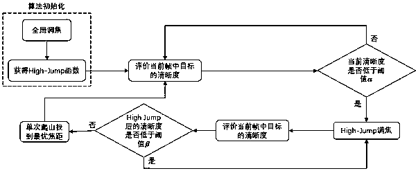
[0032] Such as figure 1 As shown, an autofocus method based on an electro-hydraulic adjustable focus lens includes the following steps:

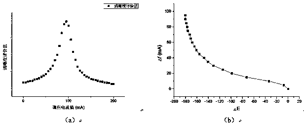
[0033] 1) The algorithm is initialized, and the High-Jump function Δf=H(ΔE) of the current target is obtained through global focusing;

[0034] 2) Evaluate the sharpness evaluation value of the target image in the current frame and determine whether it is smaller than a preset threshold α. If yes, perform step 3); if not, repeat this step;

[0035] 3) Perform High-Jump focusing;

[0036] 4) Evaluate the sharpness evaluation value of the target image in the frame after the High-Jump, and determine whether it is less than the preset threshold β. If yes, perform step 3); if not, perform step 5...


PUM


Abstract

The present invention relates to an automatic focusing method based on an electro-hydraulic lens with adjustable focus. Image definition information is employed to generate a High-Jump function to guide automatic focusing; an optimal High-Jump step length is selected according to difference between the definition of a current frame and the maximum value of a definition evaluation curve, and the step length is employed to complete High-Jump focus adjustment; and the focus length after High-Jump focus adjustment is very close to the optical focus length to greatly reduce the number of times of focus adjustment in a follow-up single hill-climbing method optimization process. The automatic focusing method is faster in focusing speed and better in focusing effect for a movement object, can fully develop the hardware advantage of the electro-hydraulic lens with adjustable focus and can achieve accurate focusing of the movement object through High-Jump continuous jump.

Description

technical field [0001] The invention relates to an automatic focus method based on an electro-hydraulic adjustable focus lens. Background technique [0002] Autofocus algorithm has become a research hotspot since the 1960s, and its main task is to achieve autofocus without external intervention and provide observers with images with clear edges and rich details. At present, although autofocus technology has been popularized in digital cameras and mobile phone cameras, there are still some problems in the existing autofocus technology in the fields of industrial machine vision, various precision measurement and high-precision projection instruments: the focus accuracy is not high , it is easy to cause misfocusing; the focusing stability is not high, and it is easily affected by environmental noise; the degree of intelligent focusing and real-time performance need to be improved. The traditional focusing system also has some problems in terms of hardware: there is an error in...

Claims


Application Information

Patent Timeline
Patent Type & Authority Applications(China)
IPC IPC(8): G02B7/28G02B3/14
CPCG02B7/28G02B3/14
Inventor 夏瑞隆李恒宇刘靖逸曹宁丁长权
Owner SHANGHAI UNIV
Learn More