A Relay Grouting Technology for 200m Box Girder Hole
A tunnel and box girder technology, applied in the field of relay grouting for 200m box girder tunnels, can solve problems such as failure to fill in, grouting pipes and outlet pipes burst, and failure to successfully complete grouting for 200m tunnels, so as to improve grouting speed and reduce pressure , to ensure the overall effect
- Summary
- Abstract
- Description
- Claims
- Application Information
AI Technical Summary
Problems solved by technology
Method used
Image


Examples
Embodiment 1
[0057] A 200m box girder tunnel relay grouting process, comprising the following steps:
[0058] ①Install the grout cap
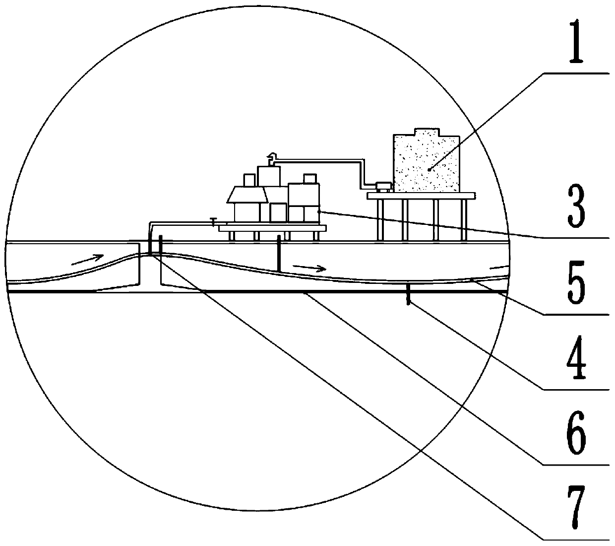
[0059] Before grouting, on-site technicians should strictly check the bolt connection between the grouting cap and the bell mouth, the connection between the grout hole and the grout pipe 4, and the connection between the valve and the grout pipe 4. Loosening is not allowed at all connections to prevent pressure Grout leakage occurs during the grouting process, while ensuring good airtightness of the entire prestressed channel 5;
[0060] ②Clean the prestressed tunnel
[0061] Use water to clean the dust and dirt on the surface of the tunnel 5 and the prestressed tendons. On the one hand, it is to check whether the slurry outlet pipe 4 is blocked. Inject clean water directly from one end of the tunnel 5 until the slurry outlet pipe 4 at the other end flows out of the clean water and stop water injection, and use an air compressor to press air from one sid...
Embodiment 2
[0080] A 200m box girder tunnel relay grouting process, comprising the following steps:
[0081] ①Install the grout cap
[0082] Before grouting, on-site technicians should strictly check the bolt connection between the grouting cap and the bell mouth, the connection between the grout hole and the grout pipe 4, and the connection between the valve and the grout pipe 4. Loosening is not allowed at all connections to prevent pressure Grout leakage occurs during the grouting process, while ensuring good airtightness of the entire prestressed channel 5;
[0083] ②Clean the prestressed tunnel
[0084] Use water to clean the dust and dirt on the surface of the tunnel 5 and the prestressed tendons. On the one hand, it is to check whether the slurry outlet pipe 4 is blocked. Inject clean water directly from one end of the tunnel 5 until the slurry outlet pipe 4 at the other end flows out of the clean water and stop water injection, and use an air compressor to press air from one sid...
Embodiment 3
[0103] A 200m box girder tunnel relay grouting process, comprising the following steps:
[0104] ①Install the grout cap
[0105] Before grouting, on-site technicians should strictly check the bolt connection between the grouting cap and the bell mouth, the connection between the grout hole and the grout pipe 4, and the connection between the valve and the grout pipe 4. Loosening is not allowed at all connections to prevent pressure Grout leakage occurs during the grouting process, while ensuring good airtightness of the entire prestressed channel 5;
[0106] ②Clean the prestressed tunnel
[0107] Use water to clean the dust and dirt on the surface of the tunnel 5 and the prestressed tendons. On the one hand, it is to check whether the slurry outlet pipe 4 is blocked. Inject clean water directly from one end of the tunnel 5 until the slurry outlet pipe 4 at the other end flows out of the clean water and stop water injection, and use an air compressor to press air from one sid...
PUM
 Abstract
Description
Claims
Application Information
 - R&D
- Intellectual Property
- Life Sciences
- Materials
- Tech Scout
- Unparalleled Data Quality
- Higher Quality Content
- 60% Fewer Hallucinations
Browse by: Latest US Patents, China's latest patents, Technical Efficacy Thesaurus, Application Domain, Technology Topic, Popular Technical Reports.
© 2025 PatSnap. All rights reserved.Legal|Privacy policy|Modern Slavery Act Transparency Statement|Sitemap|About US| Contact US: help@patsnap.com