Aerial photographing unmanned aerial vehicle with contraction-function landing gear

A technology of shrinking function and landing gear, which is applied in the field of aerial photography drones, can solve the problems of affecting the control stability of drones, the camera lens is easily covered with fog, and the air resistance of drones is increased, so as to achieve fast response and reduce Small shock resistance and reduced air resistance

Inactive Publication Date: 2018-09-11
QINGYUAN JUJIN TECH CO LTD
View PDF0 Cites 6 Cited by
  • Summary
  • Abstract
  • Description
  • Claims
  • Application Information

AI Technical Summary

Problems solved by technology

[0002] Aerial UAV is a kind of UAV, which is mainly used for long-time, large-angle, and long-distance shooting of video images on the ground in the air. Therefore, it is widely used in agriculture, meteorology, geography, scientific research and other fields. However, the traditional Aerial drone cameras work in a humid environment, and the camera lens is easily covered with fog, which affects the shooting effect, and the existing drone landing gear is usually fixed and cannot be retracted, which not only causes the drone to fly during the flight The air resistance in the middle increases, and due to the disturbance of the airflow by the landing gear, it may affect the control stability of the UAV in severe cases

Method used


Image

  • Aerial photographing unmanned aerial vehicle with contraction-function landing gear
  • Aerial photographing unmanned aerial vehicle with contraction-function landing gear
  • Aerial photographing unmanned aerial vehicle with contraction-function landing gear

Examples


Embodiment Construction

[0017] The preferred embodiments of the present invention will be described below in conjunction with the accompanying drawings. It should be understood that the preferred embodiments described here are only used to illustrate and explain the present invention, and are not intended to limit the present invention.

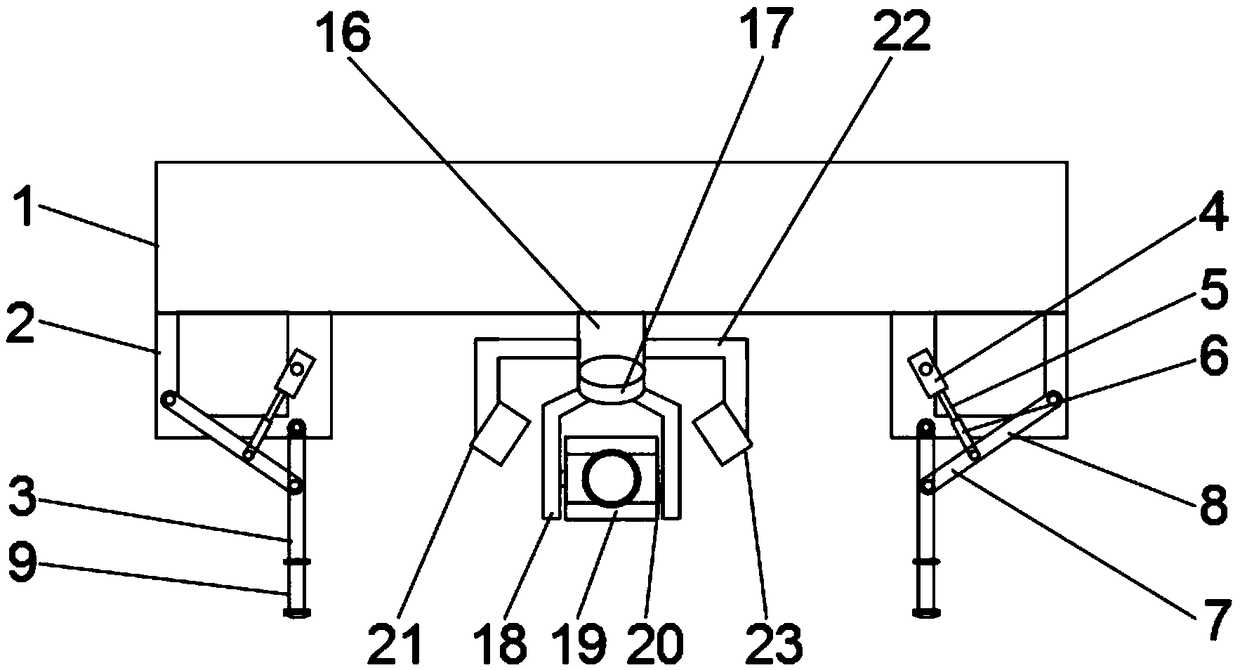
[0018] Example: such as Figure 1-4 As shown, the present invention provides a technical solution, an aerial photography UAV with retractable landing gear, including a body 1, a retractable frame 2, a support rod 3, a motor 4, a threaded rod 5, a sleeve 6, a first connection Rod 7, second connecting rod 8, buffer device 9, connecting column 16, rotating table 17, bracket 18, camera 19, connecting shaft 20 and defogging device 21, the bottom of body 1 is welded with shrinkage frame 2, and the lower end of shrinkage frame 2 A support rod 3 is provided, and a motor 4 is installed on the upper side of the support rod 3 relative to the middle part of the shrink frame 2, ...


PUM


Abstract

The invention discloses an aerial photographing unmanned aerial vehicle with a contraction-function landing gear. The aerial photographing unmanned aerial vehicle comprises a machine body, contractionframes, supporting rods, motors, threaded rods, sleeves, buffer devices, a video camera and a defogging device, wherein contraction frame are welded to the bottom of the vehicle body. The aerial photographing unmanned aerial vehicle disclosed by the invention has a scientific and reasonable structure; the motors are matched with the threaded rods and the sleeves to serve as a collecting and releasing power part; furthermore, the motors are stepping motors; meanwhile, the motors have good control performance; by controlling the motors to rotate forwards, the threaded rods rotate forwards to drive the sleeves to rotate, and the supporting rods contract to reduce air resistance in a flying process; by controlling the motors to rotate reversely, the threaded rods rotates reversely to drive the sleeves to rotate, and the supporting rods can be expanded; air is blown by fans to be blown to the video camera along an air inlet pipe; meanwhile, a heating pipe is heated, the air can be heated by the heating pipe to form warm braw when the air passes through the heating pipe, and fog on a camera lens of the video camera is evaporated by the warm braw; thus, a defogging function is achieved.

Description

technical field [0001] The invention relates to the technical field of unmanned aerial vehicles, in particular to an aerial photography unmanned aerial vehicle with retractable landing gear. Background technique [0002] Aerial UAV is a kind of UAV, which is mainly used for long-time, large-angle, and long-distance shooting of video images on the ground in the air. Therefore, it is widely used in agriculture, meteorology, geography, scientific research and other fields. However, the traditional Aerial drone cameras work in a humid environment, and the camera lens is easily covered with fog, which affects the shooting effect, and the existing drone landing gear is usually fixed and cannot be retracted, which not only causes the drone to fly during the flight The air resistance in the middle increases, and due to the disturbance of the airflow by the landing gear, it may affect the control stability of the UAV in severe cases. Contents of the invention [0003] The object o...

Claims


Application Information

Patent Timeline
IPC IPC(8): B64C25/04B64C25/12B64C25/24B64C25/62B64C25/64B64D47/08
CPCB64C25/04B64C25/12B64C25/24B64C25/62B64C25/64B64D47/08
Inventor 杨毅勋雷敏珊
Owner QINGYUAN JUJIN TECH CO LTD
Why Eureka
Try Eureka