
A Keyhole-less Friction Stir Spot Welding Machine

A friction stir and spot welding machine technology, applied in welding equipment, non-electric welding equipment, metal processing equipment, etc., can solve the problem of less professional friction stir welding machines

Active Publication Date: 2021-05-18
JIANGSU UNIV OF TECH
View PDF6 Cites 0 Cited by
  • Summary
  • Abstract
  • Description
  • Claims
  • Application Information

AI Technical Summary

Problems solved by technology

However, with the rapid development of the aviation industry and the automobile industry, there is a huge demand for friction stir welding machines suitable for welding light metals and dissimilar metals. However, since friction stir welding is still a new welding method, most friction stir welding machines are modified from drilling and milling machines. , There are few professional friction stir welding machines with functional directionality and pertinence, especially for non-keyhole friction stir spot welding of dissimilar metals, and no relevant professional equipment can meet its technical requirements

Method used


Image

  • A Keyhole-less Friction Stir Spot Welding Machine
  • A Keyhole-less Friction Stir Spot Welding Machine
  • A Keyhole-less Friction Stir Spot Welding Machine

Examples


Embodiment Construction

[0010] The specific implementation manners of the present invention will be described in further detail below in conjunction with the accompanying drawings.

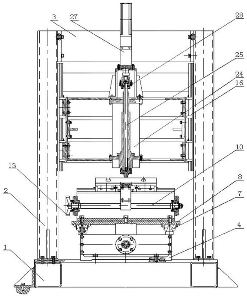
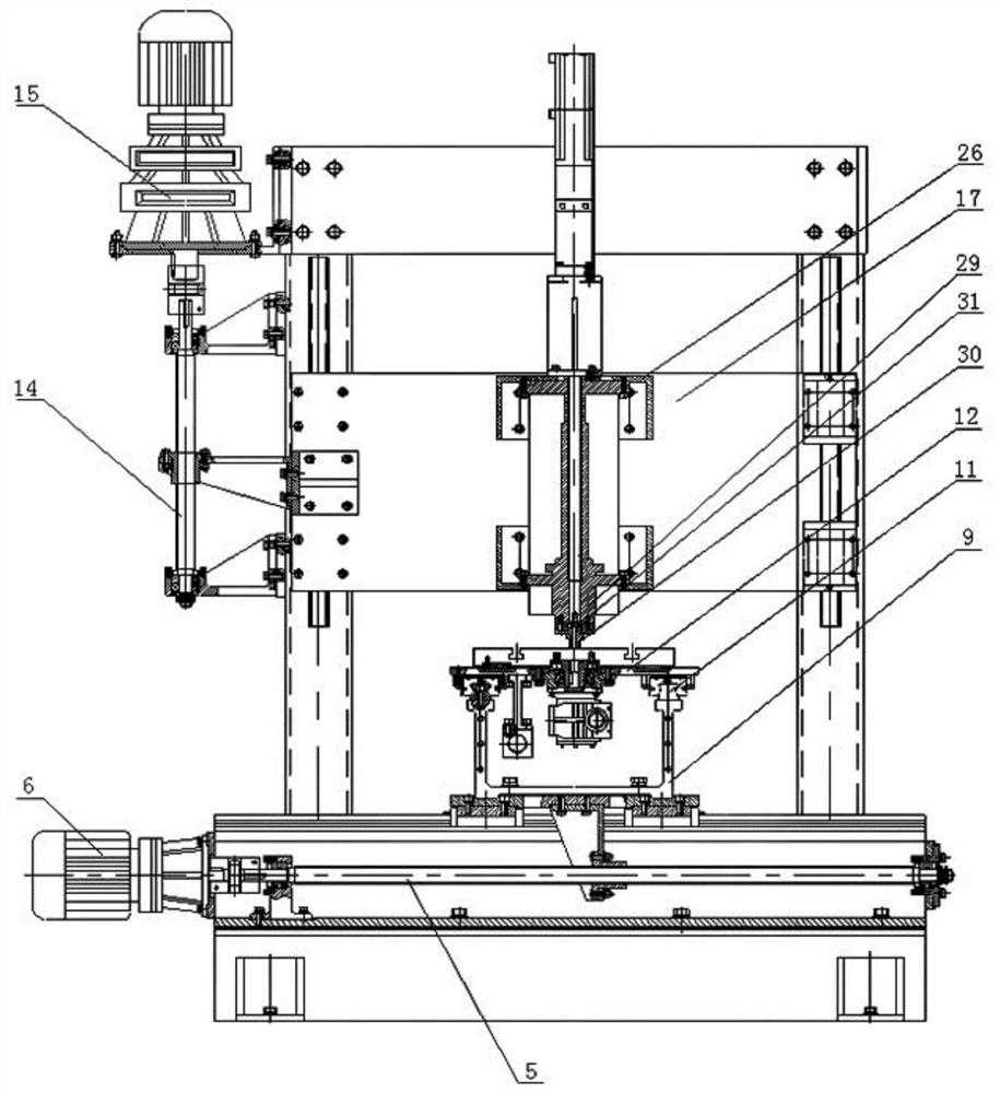
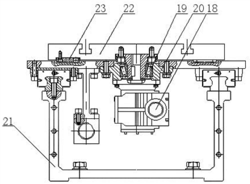
[0011] Figure 1 to Figure 3 A schematic diagram of the assembly structure of the present invention is shown. Such as Figure 1 to Figure 3As shown, the present invention provides a keyhole-free friction stir spot welding machine. It includes a frame, an X-axis mechanism, a Y-axis mechanism, a Z-axis mechanism, a rotary table 22 mechanism, a spindle system and a stirring head system. The frame includes a base 1, a column 2 and a top cover 3, and the column 2 is set on the base 1 , the number of columns 2 is four, the top cover 3 is set on the column 2, the X-axis mechanism and the Z-axis mechanism are set on the frame, the Y-axis mechanism is set on the X-axis mechanism, and the spindle system and the stirring head system are set on the Z-axis mechanism , the frame is equipped with a rotary table 22 mechanism, the spi...


PUM


Abstract

The invention discloses a keyhole-less friction stir spot welding machine. It includes a frame, an X-axis mechanism, a Y-axis mechanism, a Z-axis mechanism, a rotary table mechanism, a spindle system and a stirring head system. The frame includes a base, a column and a top cover. The top cover is set on the column, the X-axis mechanism and the Z-axis mechanism are set on the frame, the Y-axis mechanism is set on the X-axis mechanism, the spindle system and the stirring head system are set on the Z-axis mechanism, and the rotary table mechanism is set in the frame. , the spindle system and the mixing head system are connected. It has the characteristics of simple structure, high welding precision, convenient operation by personnel and safe and reliable work. During the welding process, not only the stirring head rotates, but also the workpiece to be welded can rotate in the same direction or in the opposite direction.

Description

technical field [0001] The invention belongs to the technical field of friction stir welding machines, in particular to a keyhole-less friction stir spot welding machine. Background technique [0002] The existing stirring head of friction stir spot welding is mainly composed of three parts, which are the innermost probe, the middle sleeve and the outermost jacket. Wherein, the jacket is fixed during welding and does not rotate, while the sleeve of the middle layer and the probe of the innermost layer both rotate and move relative to each other along the axial direction during welding. In the Chinese invention patent specification CN108555433A, a dual-mode keyhole-less friction stir spot welding equipment is disclosed, which includes an outer shell, a handle is provided on the top of the outer shell, and a power motor is installed in the outer shell; The cylinder coupling is connected to the driving shaft, and the driving shaft meshes with the driven shaft gear on the drive...

Claims


Application Information

Patent Timeline
Patent Type & Authority Patents(China)
IPC IPC(8): B23K20/12B23K20/26
CPCB23K20/12B23K20/26
Inventor 刘骁张云龙从孟启张扬陈逸王洪金孙顺平李小平于赟
Owner JIANGSU UNIV OF TECH
Learn More