Automobile torque distribution method, device and system

A torque distribution and automotive technology, applied in the automotive field, can solve the problems of reducing driver comfort and vehicle instability, and achieve the effects of improving driving comfort, consistent vehicle wheel resistance torque, and constant braking deceleration

Active Publication Date: 2020-09-08
GEELY AUTOMOBILE INST NINGBO CO LTD +1
View PDF8 Cites 0 Cited by
  • Summary
  • Abstract
  • Description
  • Claims
  • Application Information

AI Technical Summary

Problems solved by technology

[0004] In view of this, the object of the present invention is to provide an automobile torque distribution method, device and system to alleviate the technical problems that the existing braking energy recovery system tends to cause the vehicle to run unstable and reduce the comfort of the driver

Method used


Image

  • Automobile torque distribution method, device and system
  • Automobile torque distribution method, device and system
  • Automobile torque distribution method, device and system

Examples


Embodiment 1

[0035] An embodiment of the present invention provides a vehicle torque distribution method, which can be applied to a vehicle controller of a hybrid power system, and the vehicle controller can be a vehicle controller based on an ESP (Electronic Stability Program, Electronic Stability Program) system, ESP The system can be composed of a control unit and a steering sensor (monitoring the steering angle of the steering wheel), a wheel sensor (monitoring the speed rotation of each wheel), a sideslip sensor (monitoring the state of the car body rotating around the vertical axis), and a lateral acceleration sensor (monitoring when the car is turning). The centrifugal force) and other components, through the analysis of the vehicle driving state information transmitted from each sensor, and then issue a correction command to help the vehicle maintain a dynamic balance, so that the vehicle maintains the best stability under various conditions.

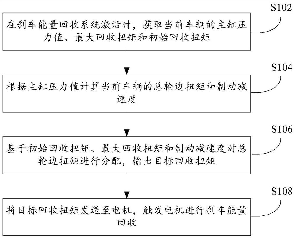
[0036] Such as figure 1 A flow chart ...

Embodiment 2

[0075] On the basis of the above-mentioned embodiments, the embodiment of the present invention also provides an automobile torque distribution device, which is arranged in the vehicle controller of the hybrid power system, such as Figure 7 A structural schematic diagram of a vehicle torque distribution device shown, the device includes:

[0076] The first obtaining module 70 is used to obtain the master cylinder pressure value, the maximum recovery torque and the initial recovery torque of the current vehicle when the braking energy recovery system is activated;

[0077] A calculation module 72, configured to calculate the total wheel torque and braking deceleration of the current vehicle according to the master cylinder pressure value;

[0078] A distribution module 74, configured to distribute the total wheel torque based on the initial recovery torque, the maximum recovery torque and the braking deceleration, and output a target recovery torque;

[0079] The recovery mod...


PUM


Abstract

The invention provides an automobile torque distributing method, device and system, and relates to the technical field of automobiles. The method comprises the steps that when a braking energy recovery system is activated, the pressure value of a master cylinder, maximum recovery torque and initial recovery torque of a current automobile are obtained; the total wheel side torque and braking deceleration of the current automobile are calculated according to the pressure value of the master cylinder; the total wheel side torque is distributed based on the initial recovery torque, the maximum recovery torque and the braking deceleration to output target recovery torque; the target recovery torque is transferred to a motor, and the motor is triggered to recover braking energy. By means of theautomobile torque distributing method, device and system, the wheel side resistance torque is uniform under the same depth of a braking pedal regardless of the existence of a braking energy recovery function to make the braking deceleration constant, avoid the sudden change of the deceleration of the automobile and increase the stability of the driving of the automobile to further increase the driving comfort of a driver.

Description

technical field [0001] The invention relates to the technical field of automobiles, in particular to an automobile torque distribution method, device and system. Background technique [0002] With the increasing popularization of hybrid electric vehicles, the number of hybrid electric vehicles is increasing day by day. The energy saving and battery life of hybrid electric vehicles have been paid great attention by domestic and foreign automotive engineering circles. In order to protect the environment and use resources rationally, it is necessary to reduce the resource consumption of hybrid electric vehicles. Usually, the energy lost when the hybrid electric vehicle brakes can be recovered to improve the battery life of the hybrid electric vehicle. [0003] However, when the existing braking energy recovery system is activated, its energy recovery torque is usually kept constant, which easily leads to sudden changes in vehicle deceleration, resulting in unstable driving of ...

Claims


Application Information

Patent Timeline
Patent Type & Authority Patents(China)
IPC IPC(8): B60W20/14B60W10/08B60W10/26B60L7/10
CPCB60L7/10B60W10/08B60W10/26B60W20/14B60W2510/0604B60W2510/0638B60W2510/1005B60W2510/244B60W2520/10B60W2540/12B60W2710/08B60W2710/242
Inventor 吴孝勤阳向兰吕登科
Owner GEELY AUTOMOBILE INST NINGBO CO LTD
Why Eureka
Try Eureka