
Machining equipment for communication cable

A technology for processing equipment and communication cables, which is applied in the field of electric power, can solve problems such as high labor intensity, long time consumption, cumbersome and complicated process, etc., and achieve the effects of reducing labor intensity, improving work efficiency, and simple operation

Active Publication Date: 2018-09-11
以太龙精密机械江苏有限公司
View PDF5 Cites 20 Cited by
  • Summary
  • Abstract
  • Description
  • Claims
  • Application Information

AI Technical Summary

Problems solved by technology

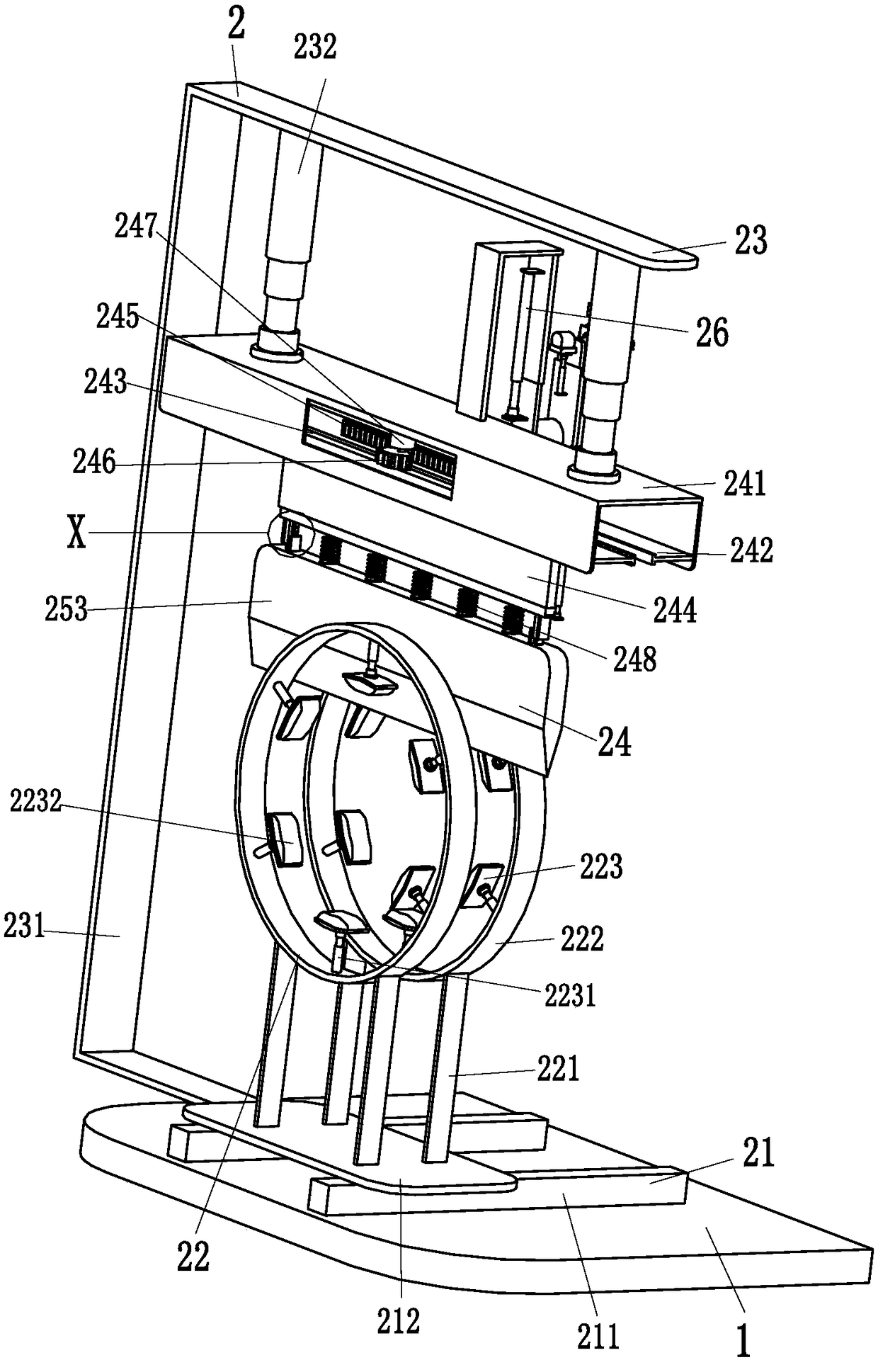
[0003] In order to solve the above problems, the present invention provides a processing equipment for communication cables, which can solve the need to manually limit the communication cable sleeves and then cut them in the processing process of the existing communication cable sleeves. During the casing, personnel need to grasp the communication cable casings of different structures in different ways, and the manual grasping is single and unstable. When cutting, it is easy to deviate from the position when cutting manually, resulting in uneven nozzles, and there will be burrs after cutting. , the process takes a long time, the labor intensity is high, and the efficiency is low. It can realize the function of automatic limit and cutting of the communication cable sleeve, and carry out targeted limit on the communication cable sleeve of different structures, and limit the position of multiple parts at the same time. , multi-position limit at the same time, automatic grasping, automatic cutting, nozzle flattening, automatic deburring, no manual operation, short time-consuming, and has the advantages of simple operation, low labor intensity and high work efficiency

Method used


Image

  • Machining equipment for communication cable
  • Machining equipment for communication cable
  • Machining equipment for communication cable

Examples


Embodiment Construction

[0032] In order to make the technical means, creative features, goals and effects achieved by the present invention easy to understand, the present invention will be further described below in conjunction with specific illustrations. It should be noted that, in the case of no conflict, the embodiments in the present application and the features in the embodiments can be combined with each other.

[0033] Such as Figure 1 to Figure 6 As shown, in order to achieve the above object, the present invention adopts the following technical solutions: a processing equipment for communication cables, including a main board 1, a cutting and deburring device 2, a middle limiting device 3 and an end limiting device 4, the main board 1. A cutting and deburring device 2 is installed at the front end, a middle limiting device 3 is installed at the middle of the main board 1, and an end limiting device 4 is installed at the rear end of the main board 1.

[0034] The cutting and deburring dev...


PUM


Abstract

The invention relates to machining equipment for a communication cable. The machining equipment comprises a main plate, a cutting and deburring device, a middle limiting device and an end limiting device, the cutting and deburring device is installed at the front end of the main plate, the middle limiting device is installed in the middle of the main plate, and the end limiting device is installedat the back end of the main plate. According to the machining equipment for the communication cable, the problems that in the existing communication cable sleeve machining process, communication cable sleeves need to be manually limited and then cut, the process is tedious and complex, when the communication cable sleeves are limited, workers need to grab the communication cable sleeves with different structures in different modes, manual grabbing is single and unstable, when cutting is conducted, sleeve openings are likely to be uneven due to the fact that the positions are prone to deviating when manual cutting is conducted, burrs can be generated after cutting, the time consumed by the process is long, the labor intensity is high, and the efficiency is low can be solved, and the automatic limiting and cutting functions on the communication cable sleeves can be achieved.

Description

technical field [0001] The invention relates to the field of electric power, in particular to a processing equipment for communication cables. Background technique [0002] Communication cable casing is a new type of casing material popularized and used in electric power engineering. It has high strength and high rigidity. It is used for direct burial under the roadway without adding a concrete protective layer. It can speed up the construction progress of the cable project. The pipe is flexible. It can resist the damage caused by external heavy pressure and foundation settlement. It is corrosion-resistant and has a long service life. It can be used in humid saline-alkaline areas. Combustion has good anti-interference performance of external signals, so it is widely used in the power field. However, the cutting of communication cable sleeves is cumbersome and complicated. How to process communication cable sleeves has become a big problem. Nowadays, communication cables need...

Claims


Application Information

Patent Timeline
IPC IPC(8): B26D7/04B26D7/01B26D1/08B24B9/02
CPCB24B9/02B26D1/08B26D7/01B26D7/04B26D2007/013
Inventor 张美姣
Owner 以太龙精密机械江苏有限公司
Learn More