
Improved three-axis power tool tower turning and milling composite machine

A power turret and compound machine technology, applied in the field of compound machines, can solve problems such as inconvenient use, low work efficiency, and complex structure

Active Publication Date: 2018-09-07
杭州祥龙汽车配件有限公司
View PDF8 Cites 0 Cited by
  • Summary
  • Abstract
  • Description
  • Claims
  • Application Information

AI Technical Summary

Problems solved by technology

[0002] Machining refers to the process of changing the shape or performance of a workpiece through a mechanical device. According to the difference in processing methods, it can be divided into cutting processing and pressure processing. Compound processing is currently the most popular processing technology in the world in the field of mechanical processing. One of them is an advanced manufacturing technology. Composite machining is to realize several different processing technologies on one machine tool. Composite machining is the most widely used and the most difficult. It is turning-milling combined machining. The turning-milling combined machining center is equivalent to A combination of a CNC lathe and a machining center. At the same time, the power turret is an important part of the combined turning and milling process. With the development of science and technology, the turning and milling machine is also developing and improving. Among them, the power turret Turning and milling compound machines are also widely used, but the power turret turning and milling compound machines on the market still have low work efficiency, complex structure, poor stability, and inconvenient use. In the prior art, for example, the application number is 201720024726.8 The patent for the invention includes a turning-milling composite machine body. Two conveyor belts are symmetrically arranged on both ends of the upper surface of the turning-milling composite body. The driving wheels of the two conveyor belts are connected to the motor through a belt, and the motor is fixed and installed on the motor frame. On the center of the lower surface of the bottom plate of the turning-milling compound body, a vertical spindle arm is arranged in the middle of the turning-milling compound body, the vertical spindle arm is arranged between two conveyor belts, and the top of the vertical spindle arm is provided with a double turret The two ends of the double-knife tower plate are connected with two power turrets through telescopic columns, and the two power turrets are connected with a tool changer through a telescopic rod. Knives, the four corners of the bottom of the turning and milling composite body are symmetrically provided with support columns. Although the invention has a simple structure, there are many shortcomings and defects. In the existing equipment, there are defects in the design of the cutter head. The connection between the cutter head and the milling cutter Unstable, the milling cutter is prone to shaking during use, which affects the processing accuracy, poor stability, and many scrapped parts, which increases the processing cost. The depth is not enough and the processing efficiency is low. In view of these situations, in order to avoid the above technical problems, it is necessary to provide an improved three-axis power turret turning and milling machine to overcome the defects in the prior art.

Method used


Image

  • Improved three-axis power tool tower turning and milling composite machine
  • Improved three-axis power tool tower turning and milling composite machine
  • Improved three-axis power tool tower turning and milling composite machine

Examples


Embodiment Construction

[0019] The following will clearly and completely describe the technical solutions in the embodiments of the present invention with reference to the accompanying drawings in the embodiments of the present invention. Obviously, the described embodiments are only some, not all, embodiments of the present invention. Based on the embodiments of the present invention, all other embodiments obtained by persons of ordinary skill in the art without making creative efforts belong to the protection scope of the present invention.

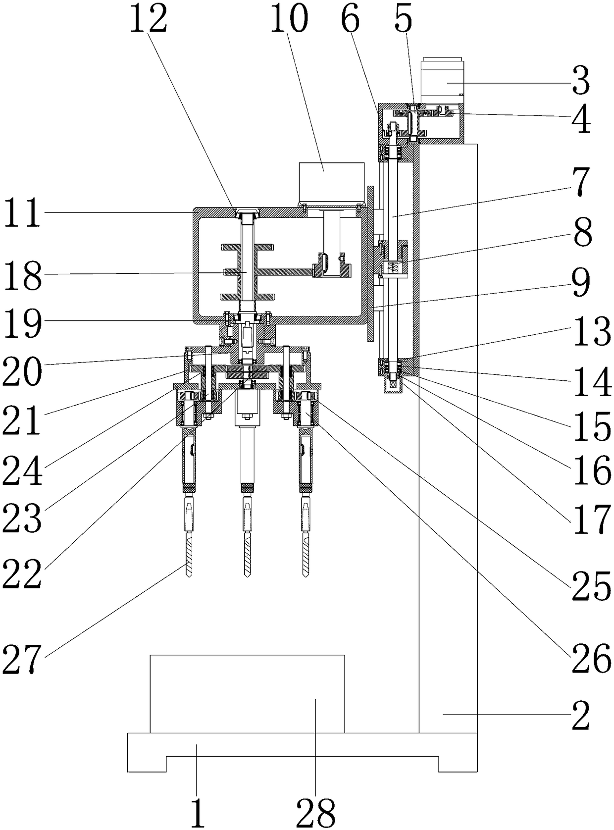
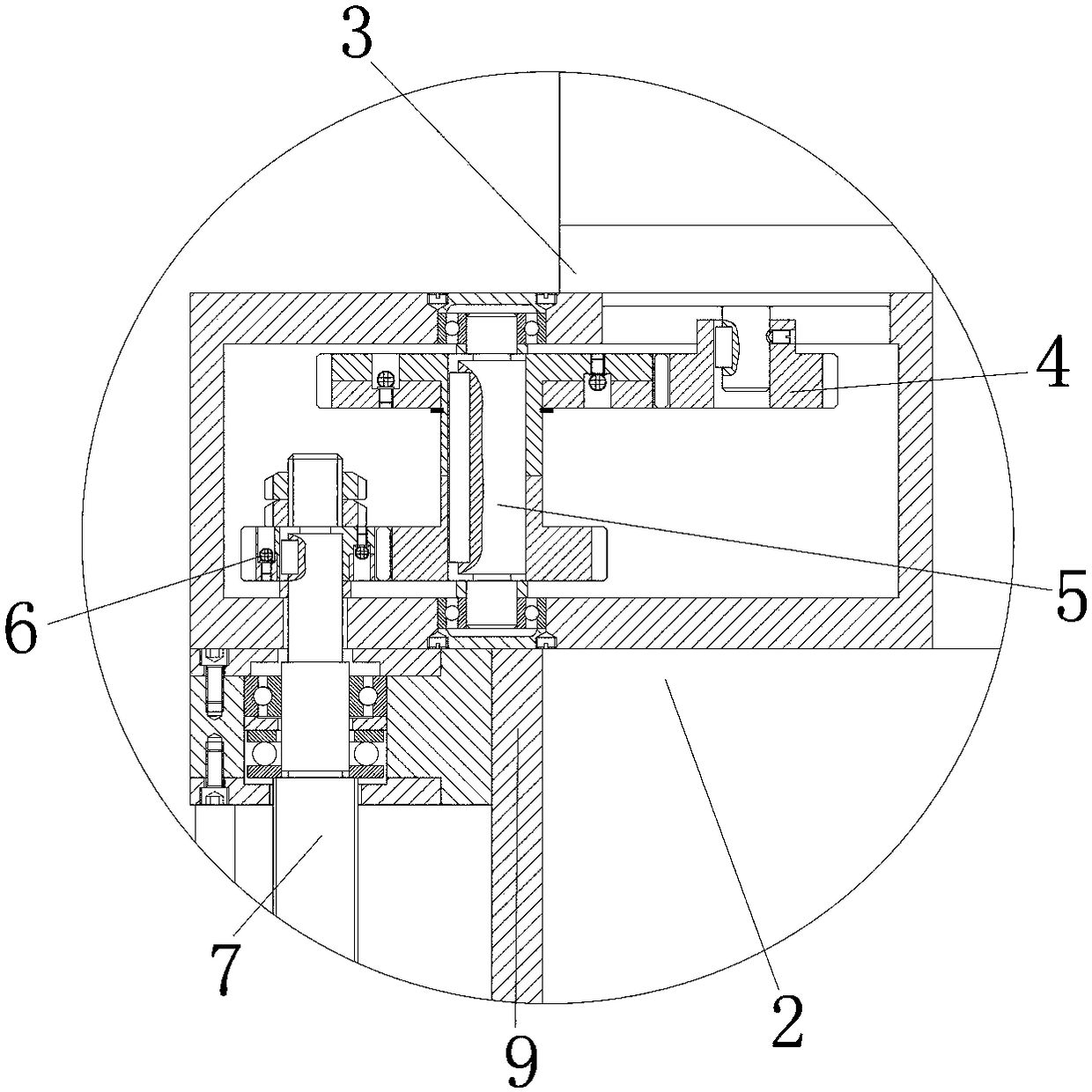
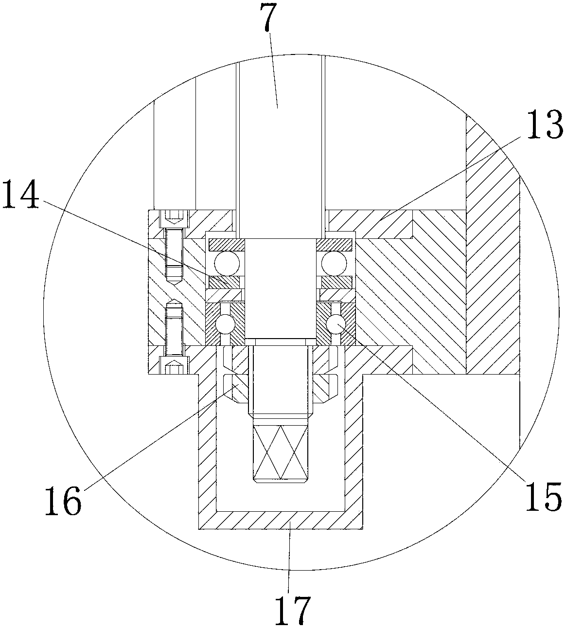
[0020] see Figure 1-3, the present invention provides a technical solution: an improved three-axis power turret turning and milling compound machine, including a base plate 1 for installing a support rod 2, and a backing plate 28 is installed on the upper surface of the base plate 1 for fixing the processing machine. , the lower surface of the backing plate 28 is connected to the upper surface of the base plate 1, the upper surface of the base plate 1 is equi...


PUM


Abstract

The invention discloses an improved three-axis power tool tower turning and milling composite machine which comprises a bottom plate. A supporting rod is mounted on the upper surface of the bottom plate, and the lower surface of the supporting rod is connected with the upper surface of the bottom plate. A first motor is mounted on the upper surface of the supporting rod, and the lower surface of the first motor is connected with the upper surface of the supporting rod. A first turning wheel is mounted on the outer wall of the first motor, and the inner wall of the first turning wheel is connected with the outer wall of the first motor. A second turning wheel is arranged on the left side of the first turning wheel, and the outer wall of the second turning wheel is connected with the inner wall of the first turning wheel in an engaged mode. According to the improved three-axis power tool tower turning and milling composite machine, through cooperation of the first motor, the first turning wheel, the second turning wheel and a third turning wheel, the product quality of the improved three-axis power tool tower turning and milling composite machine is improved, the procurement cost ofa user is reduced, resource waste of the improved three-axis power tool tower turning and milling composite machine is avoided, and the improved three-axis power tool tower turning and milling composite machine is suitable for being used and popularized.

Description

technical field [0001] The invention relates to the technical field of composite machines, in particular to an improved three-axis power turret turning and milling composite machine. Background technique [0002] Machining refers to the process of changing the shape or performance of a workpiece through a mechanical device. According to the difference in processing methods, it can be divided into cutting processing and pressure processing. Compound processing is currently the most popular processing technology in the world in the field of mechanical processing. One of them is an advanced manufacturing technology. Composite machining is to realize several different processing technologies on one machine tool. Composite machining is the most widely used and the most difficult. It is turning-milling combined machining. The turning-milling combined machining center is equivalent to A combination of a CNC lathe and a machining center. At the same time, the power turret is an impo...

Claims


Application Information

Patent Timeline
IPC IPC(8): B23P23/02B23Q5/10B23Q5/28
CPCB23P23/02B23Q5/10B23Q5/28
Inventor 郭嘉川王同强
Owner 杭州祥龙汽车配件有限公司
Learn More