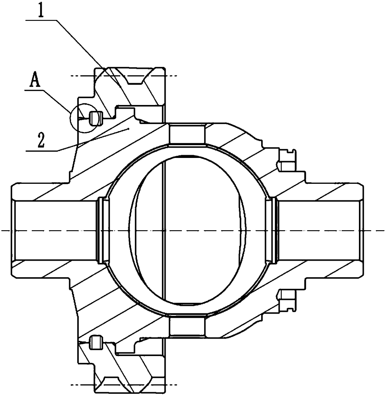
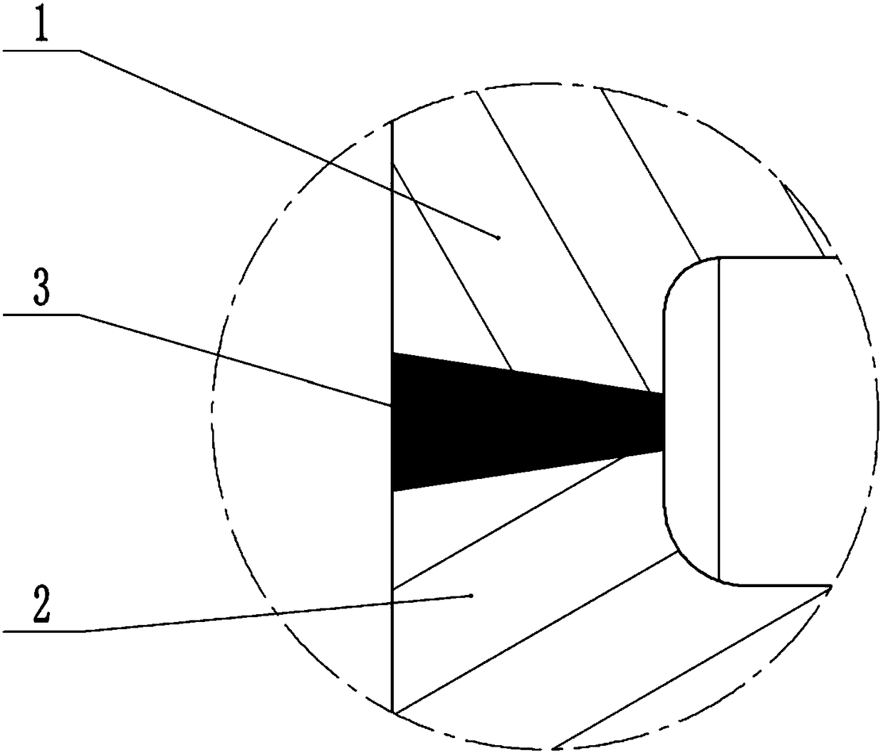
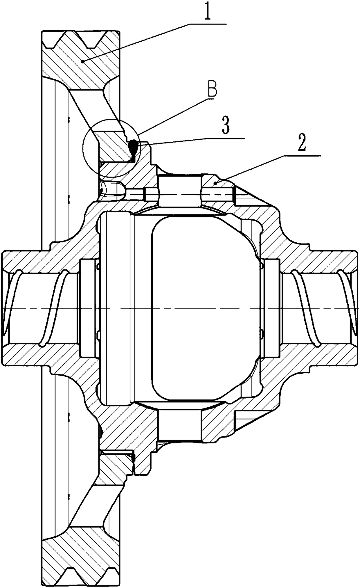
Welding technology of differential mechanism assembly
A technology of welding process and differential gear, applied in welding equipment, laser welding equipment, welding/welding/cutting items, etc., can solve the problems of difficult processing, light weight, high cost, etc., to improve production efficiency and processing accuracy , light weight and easy production
- Summary
- Abstract
- Description
- Claims
- Application Information
AI Technical Summary
Problems solved by technology
Method used
Image
Examples
Embodiment 1
[0038] A welding process for a differential gear assembly, comprising the following steps:
[0039] (1) The differential case 2 and the differential gear 1 that can be matched with each other are prepared, and the outside of the differential case 2 is a stepped shaft;
[0040] (2) Remove oil stains and carbon layers on the differential case 2 and the differential gear 1, and perform laser cleaning until the contact surfaces of the differential case 2 and the differential gear 1 are free of foreign matters and impurities;
[0041] (3) Set the shaft hole of the differential gear 1 on the stepped shaft portion with a smaller diameter of the differential case 2, and press the step between the differential gear 1 and the stepped shaft portion;
[0042] (4) Fix the differential gear 1 and the differential case 2 with a clamp, and fill the axial contact surface of the differential case 2 and the differential gear 1 with 1mm iron-nickel alloy welding wire using a welding wire filling ...
Embodiment 2
[0048]The difference between this embodiment and Embodiment 1 is that in step (4), a welding wire filling mechanism is used to fill the axial contact surface of the differential case 2 and the differential gear 1 with a 0.6 mm iron-nickel alloy welding wire In the gap, the contact surface between the differential case 2 and the differential gear 1 is evenly divided into 3 points for spot welding.
[0049] According to the commonly used dimensions of the differential case 2 and the differential gear 1, the three points of the contact surface of the differential case 2 and the differential gear 1 can be spot welded, and the two can be well connected. Preliminary fixation; using 0.6mm iron-nickel alloy welding wire can make the welding process faster.
Embodiment 3
[0051] The difference between this embodiment and Embodiment 1 is that in step (4), a 1.3mm iron-nickel alloy welding wire is used to fill the axial contact surface of the differential case 2 and the differential gear 1 by using a welding wire filling mechanism In the gap, the contact surface between the differential case 2 and the differential gear 1 is evenly divided into 6 points for spot welding.
[0052] Spot welding the 6 points of the contact surface between the differential case 2 and the differential gear 1 can be applied to many differential assemblies. Using 1.3mm iron-nickel alloy welding wire can make the welding process more efficient. firm.
PUM
 Abstract
Description
Claims
Application Information
 - R&D
- Intellectual Property
- Life Sciences
- Materials
- Tech Scout
- Unparalleled Data Quality
- Higher Quality Content
- 60% Fewer Hallucinations
Browse by: Latest US Patents, China's latest patents, Technical Efficacy Thesaurus, Application Domain, Technology Topic, Popular Technical Reports.
© 2025 PatSnap. All rights reserved.Legal|Privacy policy|Modern Slavery Act Transparency Statement|Sitemap|About US| Contact US: help@patsnap.com


