
Expansion joint system and expansion joint method

A technology of expansion joint and tube expansion head, which is applied in the direction of heat exchange equipment, etc., can solve the problems of high positioning accuracy requirements of automatic tube expansion equipment and high requirements of expansion joint thrust.

Pending Publication Date: 2018-09-07
GREE ELECTRIC APPLIANCES INC
View PDF6 Cites 1 Cited by
  • Summary
  • Abstract
  • Description
  • Claims
  • Application Information

AI Technical Summary

Problems solved by technology

However, there are positive and negative deviations in the reprocessing process of the tube plate hole, and most of the tube plates of the heat exchanger adopt a welded structure, and there are manufacturing deviations caused by flatness, angle deflection, welding deformation, etc. in the assembly. The positioning accuracy requirements and expansion thrust requirements are very high

Method used


Image

  • Expansion joint system and expansion joint method
  • Expansion joint system and expansion joint method
  • Expansion joint system and expansion joint method

Examples


Embodiment Construction

[0043] In order to make the object, technical solution and advantages of the present invention clearer, the present invention will be further described in detail below in conjunction with the accompanying drawings and embodiments. It should be understood that the specific embodiments described here are only used to explain the present invention, not to limit the present invention.

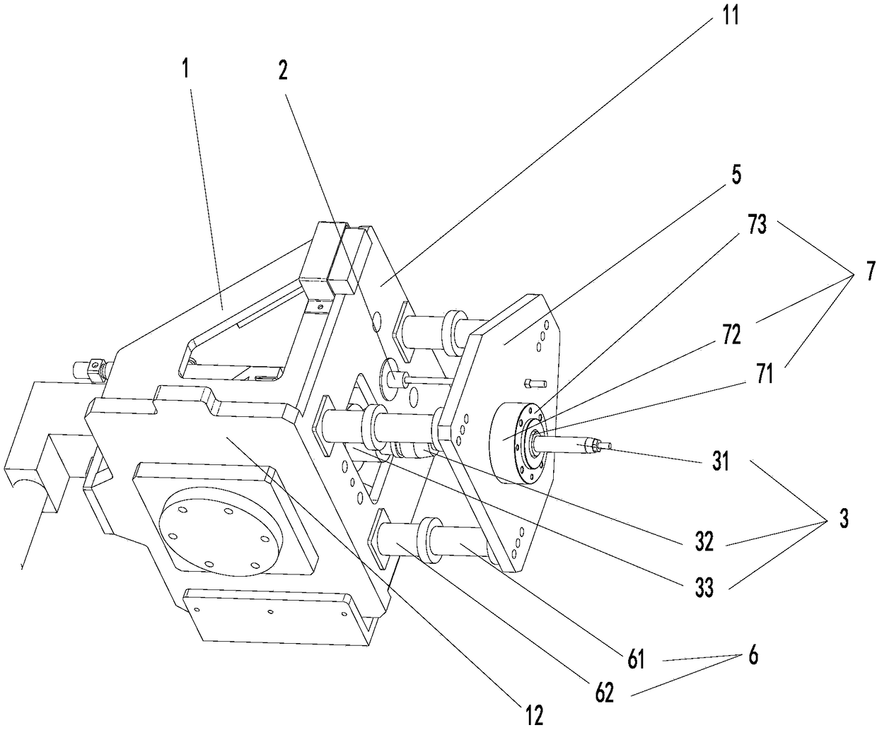
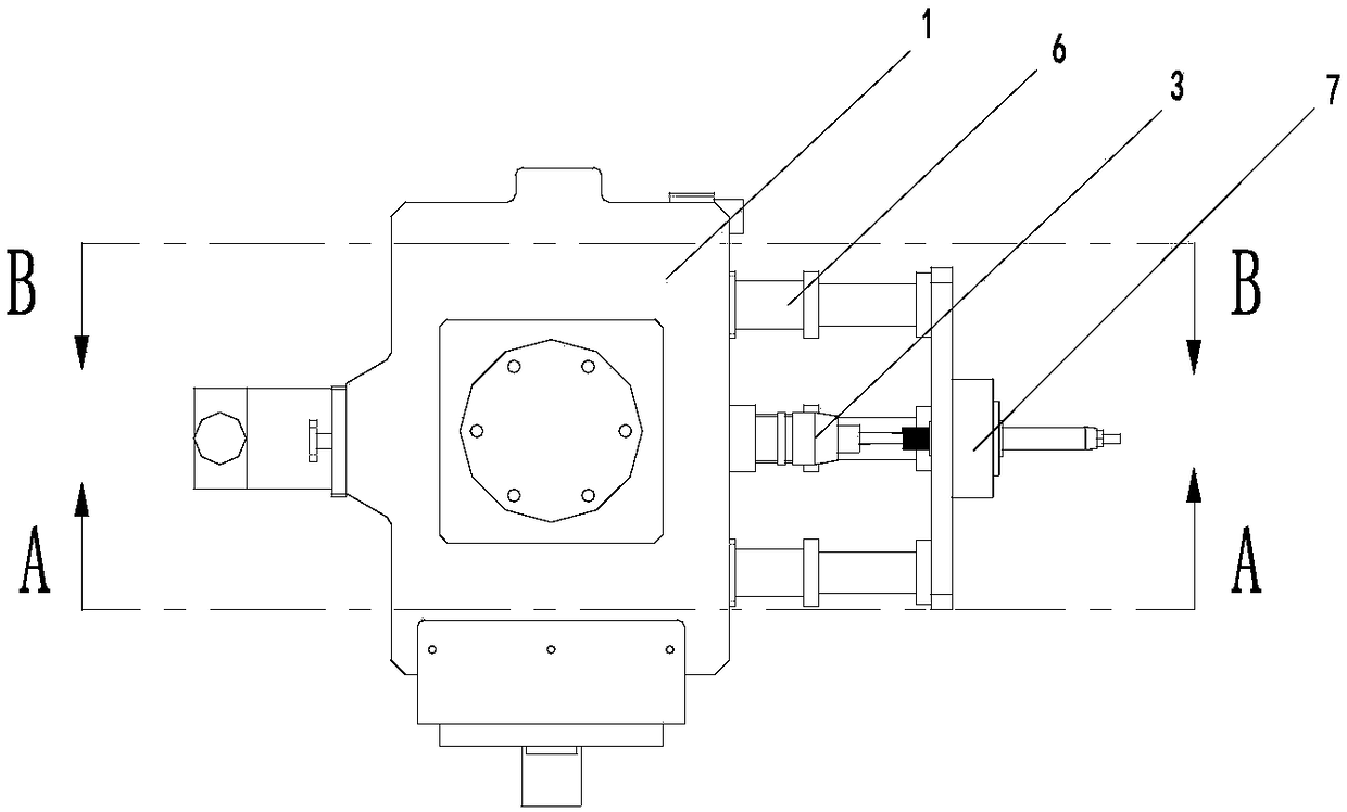
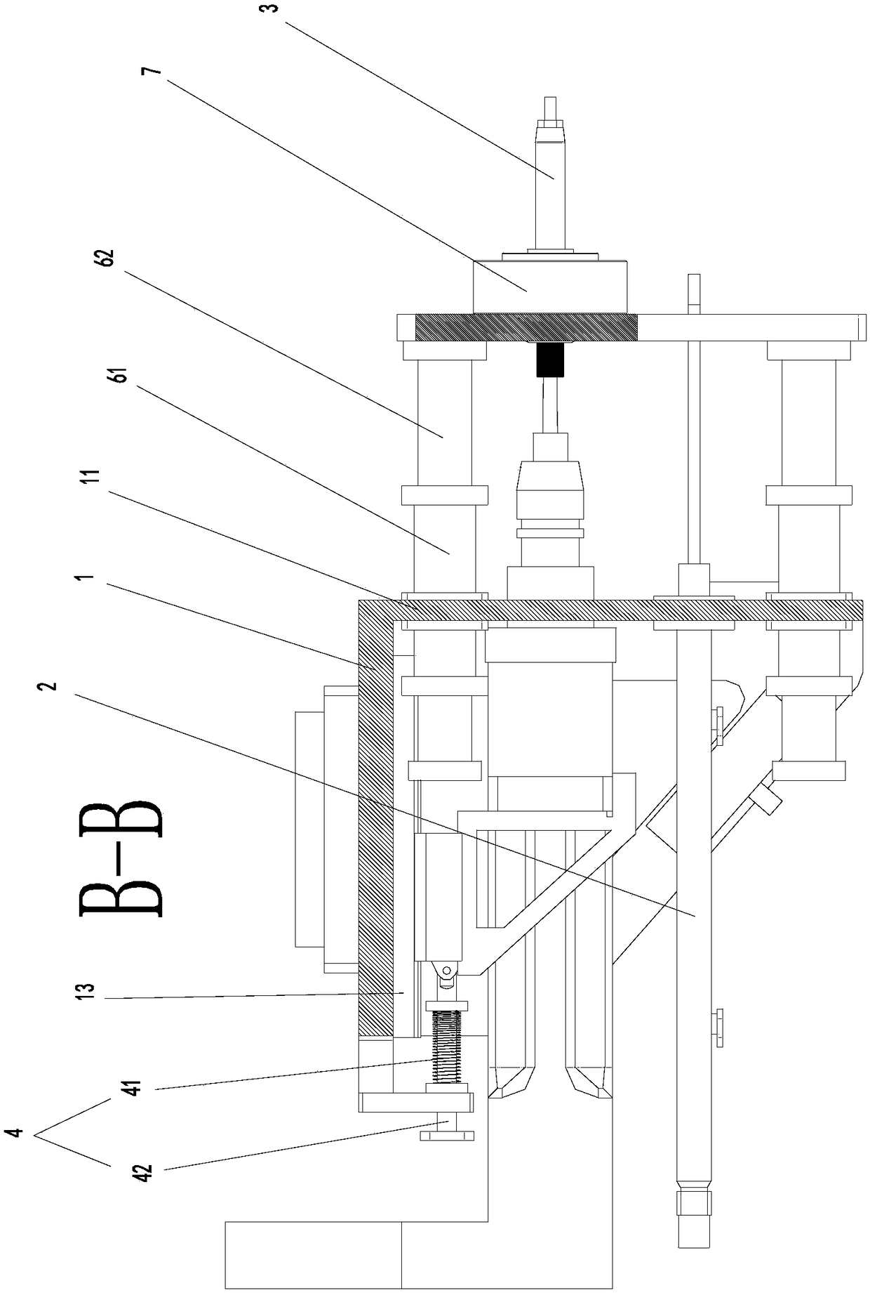
[0044] Such as Figure 1 to Figure 4 The expansion system shown includes

[0045] connect base 1;

[0046] A telescopic drive mechanism 2, the telescopic drive mechanism 2 is arranged on the connection base 1;

[0047] A tube expander 3, the tube expander 3 includes a tube expander 31 and an expansion mandrel 32, the tube expander 31 is fixedly arranged on the telescopic drive mechanism 2, and can be mounted on the telescopic drive mechanism 2 Driven away from or close to the connection base 1;

[0048] An elastic mechanism 4, the elastic mechanism 4 is fixedly arranged on the connection base 1...


PUM


Abstract

The invention provides an expansion joint system and an expansion joint method. The expansion joint system comprises a connecting base and a telescopic drive mechanism. The telescopic drive mechanismis arranged on the connecting base. According to the expansion joint system and the expansion joint method, it can be ensured that an expansion joint mandrel and a pipe expansion head can freely perform expansion joint action and it also can ensured that the expansion joint mandrel stops at any position before entering a pipe to be expanded by using the interaction of the expansion drive mechanismand an elastic mechanism, the expansion joint thrust can be controlled by using the elastic mechanism, and the thrust of an industrial robot is effectively offset, so that the expansion joint systemcan achieve the purpose of simulating manual expansion joint, it can be ensured that a pipe expansion device can act to a certain extent, and it is ensured that the pipe expansion device smoothly enters the pipe to be expanded when the axis of the pipe to be expanded has a deviation from the axis of the pipe expansion head. The linear motion of the pipe expansion device can be ensured by a pipe expansion device extension and contraction device, the expansion joint start time of the pipe expansion device can be controlled by arranging a position sensor, and the controllable purpose of expansionjoint is realized.

Description

technical field [0001] The invention relates to the field of manufacturing shell and tube heat exchangers, in particular to an expansion joint system and an expansion joint method. Background technique [0002] The tube plate of the shell-and-tube heat exchanger and the heat exchange tube are connected by strength expansion joint, welding, and expansion welding combination, and the function of the connection joint is mainly to bear pressure and seal. The strength expansion joint is a common connection method for shell and tube heat exchangers used in the central air conditioner and chemical industry. Heat exchangers for central air conditioning are mainly divided into U-shaped tube heat exchangers and fixed tube-sheet heat exchangers. The assembly form of the heat exchange tube and the tube sheet is to penetrate the heat exchange tube from the tube sheet hole on the tube sheet, the end of the heat exchange tube is flush with the end surface of the tube sheet, and then the h...

Claims


Application Information

Patent Timeline
IPC IPC(8): B21D53/08B21D39/20
CPCB21D39/20B21D53/08
Inventor 江志伟李德华邓桂成蔡小洪张望平何五润胡立超王奇钟明生
Owner GREE ELECTRIC APPLIANCES INC
Learn More