Fully-automatic zero adjustment electronic type ballistic galvanometer and zero adjustment method thereof
An inrush current and electronic technology, applied in the direction of measuring electric variables, the size/direction of magnetic field, measuring devices, etc., can solve the problems of difficult mass production and popular application, no automatic correction of compensation deviation, difficult production and other problems, to achieve Easy to promote and apply, good detection effect, easy to mass production
- Summary
- Abstract
- Description
- Claims
- Application Information
AI Technical Summary
Problems solved by technology
Method used
Image
Examples
experiment example 1
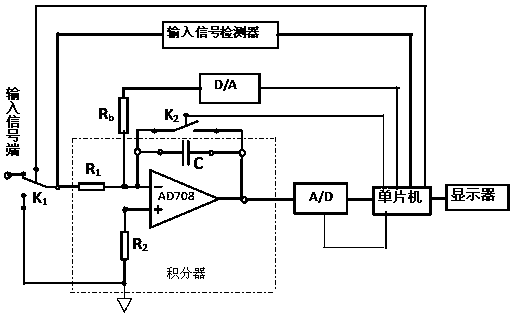
[0028] In order to verify the feasibility and reliability of the zero-adjustment method of the present invention, an operational amplifier LF353 with a large offset voltage is intentionally used (the typical value of the input offset voltage is 5mV, the input offset voltage drift is 10μV / °C, the typical value of the input bias current is 50pA, and the input The typical value of offset current is 25pA, and the typical value of open loop gain is 10 5 ) assembles a typical inverting input integrator whose integrating resistor R 1 The nominal value is 1kΩ, the nominal value of the integral capacitor C is 1μF, and the resistance R b The nominal value is 1MΩ, and the integral detection time Δt=100ms is set. An analog switch is connected in parallel with the integral capacitor, and the analog switch is controlled by a periodic positive rectangular wave voltage signal: when the rectangular wave voltage is at zero level, the analog switch is turned on to clear the integral capacitor; ...
experiment example 2
[0034] According to the experimental circuit with the same structure as described in the verification experiment example 1, randomly change a piece of LF353 to conduct the same experiment:
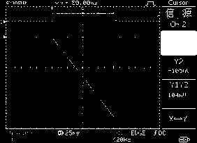
[0035] (1) Order U b =0. The digital storage oscilloscope measures the integrated output voltage U of the integrator o1 (t) Curve as attached Figure 6 As shown, the zero drift U of the integrator within the integration time Δt is measured o1 =376mv, estimate the required compensation current i b = 3.76µA and the required compensation voltage U b1 =3.76v.
[0036] (2) Set U b =U b1 =3.76v, the integrator output voltage U after coarse compensation o2 (t) Curve as attached Figure 7 As shown, the integrator at the integration time Δ t Zero drift U o2 =864mv. Find the exact value U of the required compensation voltage b = U b1 u o1 / ( U o1 –U o2 ) =3.848v.
[0037] (3) Set U b =3.848v, the integrator output voltage U after fine compensation o3 (t) Curve as attached Fig...
PUM
 Abstract
Description
Claims
Application Information
 - R&D
- Intellectual Property
- Life Sciences
- Materials
- Tech Scout
- Unparalleled Data Quality
- Higher Quality Content
- 60% Fewer Hallucinations
Browse by: Latest US Patents, China's latest patents, Technical Efficacy Thesaurus, Application Domain, Technology Topic, Popular Technical Reports.
© 2025 PatSnap. All rights reserved.Legal|Privacy policy|Modern Slavery Act Transparency Statement|Sitemap|About US| Contact US: help@patsnap.com


